I have a NOP tester for most of the CPU’s I use (and sell) just to be sure there is nothing wrong with them. I know a NOP tester does not test the chip completely but it is a good indication the chip is still working. When I was studying the MC14500 I had some questions about the timing of the signals and I build a simple circuit on a breadboard to test this. I left the circuit on the breadboard and now it is my CPU tester for the MC14500 chip.

This is the diagram of this circuit:

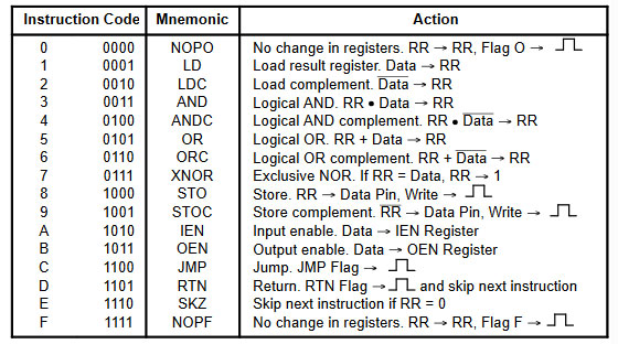
When you have all the dipswitches in the off position the instruction will be NOPO and when you toggle the first dipswitch and clock the processor, you will see the toggle of X1 and X2 and it will show that the FLAGO output has gone high. If you now put dipswitch 3 to 6 in the upwards position, this will be instruction FLAGF and after toggling the first dipswitch (clock) the FLAG0 led will go off and the FLAGF led will light up. There, your processor is working fine. You can test any instruction with this test board, also the JMP and RTN pins will light up a led.
I build this on a breadboard using three resistor arrays because they are so easy to use on a breadboard and a Led Bar, also easy to use on a breadboard because it will save you a lot of wiring. You might say that the 330 ohm resistors between the dipswitch and the + 5V are not needed and you are right. But I put them there because on a breadboard a faulty wire may cause a shortage and by adding these resistors I save myself from destroying a line of the processor with a mistake of wiring. If you do this long enough you try to be careful.