| INS1671 | Asynchronous/synchronous transmitter/receiver (National Semiconductor) Replacement for FD1671 |
| INS1771-1 | Floppy disk formatter/controller (National Semiconductor) Replacement for FD1771-1 |
| SAB1791 | Floppy disk formatter/controller SS/DD (Siemens) |
| SAB1793 | Floppy disk formatter/controller SS/DD (Siemens) |
| SAB1795 | Floppy disk formatter/controller SS/DD (Siemens) |
| SAB1797 | Floppy disk formatter/controller SS/DD (Siemens) |
| SAB2793B | Advanced floppy disk formatter/controller (Siemens) |
| SAB2797B | Advanced floppy disk formatter/controller (Siemens) |
| 7201A | Multi-protocol serial communication controller (Siemens) |
| UPD7210 | Intelligent general purpose interface bus controller (NEC) |
| 8202A | Dynamic RAM controller (Intel) |
| INS8202 | Tri-state 8-bit bus driver (National Semiconductor) |
| 8203 | Dynamic RAM controller (2164, 2117 and 2118 dram) (Intel) |
| INS8203 | Tri-state 8-bit bus driver (inverting) (National Semiconductor) |
| INS8208 | 8-bit bidirectional bus driver (National Semiconductor) |
| INS8212 | 8-bit I/O port (National Semiconductor) |
| 8216 | 4-bit bidirectional bus driver. (NEC, National Semiconductor) |
| 8224 | Clock generator and driver (Intel, National Semiconductor) |
| 8226 | 4-bit bidirectional bus driver (inverting). (NEC, National Semiconductor) |
| 8228 | System controller and bus driver (Intel, National Semiconductor) |
| 8237A | High performance programmable 4-channel DMA controller (AMD, Intel, NEC, Siemens, UMC) |
| 8238 | System controller and bus driver (Intel, National Semiconductor) |
| 8250 | Programmable asynchronous communications element (National Semiconductor, UMC) |
| 8251A | Programmable communication interface (AMD, Intel, NEC) |
| 8253 | Programmable interval timer (AMD, Intel, NEC, National Semiconductor, UMC) |
| INS8254 | 2 8-bit programmable I/O ports. (National Semiconductor) |
| 8255A | Programmable peripheral interface (AMD, Intel, NEC) |
| 82C55A | CHMOS programmable peripheral interface. (AMD, Intel, OKI, UMC) |
| INS8255 | Programmable peripheral interface (National Semiconductor) |
| 8257 | Programmable 4-channel DMA controller (Intel, NEC, National Semiconductor) |
| 8259A | Programmable interrupt controller (AMD, Intel, NEC, Siemens, UMC) |
| 82C59A | CHMOS programmable interrupt controller (AMD, Intel, OKI) |
| INS8259 | Programmable interrupt controller (National Semiconductor) |
| 8282 | Octal latch with 3-state outputs (Intel, NEC) |
| 8283 | 8-bit latch with 3-state outputs (Intel, NEC) |
| 8286 | 8-bit bus transeiver with 3-state outputs (Intel, NEC) |
| 8287 | 8-bit bus transeiver with 3-state outputs (Intel, NEC) |
| 8291A | GPIB talker/listener (Intel) |
| 8294A | Data encryption/decryption unit (Intel) |
| DP8350 | Programmable CRT controller (National Semiconductor) |
Author: admin
82xx support and peripheral chips
| 82C01 | Capacitance keyboard encoder(UMC) |
| 8202A | Dynamic RAM controller (Intel) |
| INS8202 | Tri-state 8-bit bus driver(National Semiconductor) |
| 8203 | Dynamic RAM controller(Intel) |
| 8205 | High-speed 1 out of 8 binary decoder (Intel) |
| 8206 | Error detection and correction unit (Intel) |
| 8207 | Dual-port dynamic RAM controller (Intel) |
| 8208 | Dynamic RAM controller (Intel) |
| INS8208 | 8-bit bidirectional bus driver(National Semiconductor) |
| 82C12 | 8-bit I/O port(OKI) |
| INS8212 | 8-bit I/O port (National Semiconductor) |
| 8216 | 4-bit bidirectional bus driver. (National Semiconductor) |
| 8224 | Clock generator and driver (National Semiconductor) |
| 8226 | 4-bit bidirectional bus driver. (NEC, National Semiconductor) |
| 8228 | System controller and bus driver ( Intel, National Semiconductor) |
| 8237A | High perf. 4-channel DMA controller (AMD, Intel, NEC, Siemens, UMC) |
| 8238 | System controller and bus driver (Intel, National Semiconductor) |
| 8243 | Input/Output expander(Intel, NEC) |
| 8250 | Programmable async comm, element (National Semiconductor, UMC) |
| 8251 | Programmable communication interface (AMD, National Semiconductor) |
| INS8254 | 2 8-bit programmable I/O ports. (National Semiconductor) |
| 8255A | Programmable peripheral interface(AMD, Intel, NEC) |
| INS8255 | Programmable peripheral interface (National Semiconductor) |
| SAB8256A | Programmable multifunction UART (Siemens) |
| 8257 | Programmable 4-channel DMA controller (Intel, NEC, National Semiconductor) |
| 8259A | Programmable interrupt controller (AMD, Intel, NEC, Siemens, UMC) |
| 8272A | Single/double density floppy disk controller (Intel, UMC) |
| 8273 | Programmable HLDC/SLDC protocol controller (Intel) |
| 8274 | Multi-protocol serial controller (Intel) |
| 8275H | Programmable CRT controller (Intel) |
| 8276H | Small system CRT controller(Intel) |
| 8279 | Programmable keyboard/display interface (Intel, NEC) |
| 8282 | Octal latch with 3-state outputs (Intel, NEC) |
| 8283 | 8-bit latch with 3-state outputs (Intel, NEC) |
| 8284A | Clock generator and driver (Intel, NEC) |
| 8286 | 8-bit bus transeiver with 3-state outputs (Intel, NEC) |
| 8287 | 8-bit bus transeiver with 3-state outputs (Intel, NEC) |
| 8288 | Bus controller (Intel, NEC) |
| 8289 | Bus arbiter (Intel, NEC) |
| 8291A | GPIB talker/listener(Intel) |
| 8292 | GPIB controller (Intel) |
| 8294A | Data encryption/decryption unit (Intel) |
| INS8298 | LLL BASIC interpreter for 8080A CPU (National Semiconductor) |
| 82062 | Winchester disk controller(Intel) |
| 82064 | Winchester disk controller (Intel) |
| 82077SL | Floppy disk controller (Intel) |
| 82078 | Floppy disk controller (Intel) |
| 82091AA | Advanced integrated peripheral (Intel) |
| 82188 | Integrated bus controller (Intel) |
| 82258 | Advanced 16-bit 4-channel DMA controller (Intel) |
| 82284 | Clock generator and ready interface (AMD, Intel) |
| 82C284 | CHMOS clock generator and ready interface (Intel, UMC) |
| 82288 | Bus controller (Intel) |
| 82289 | Bus arbiter (Intel) |
| 82370 | Integrated system peripheral(Intel) |
| 82380 | 32-bit DMA controller (Intel) |
| 82384 | Clock generator and reset interface (Intel) |
| 82450 | Programmable async. Comm. Element (UMC) |
| 82501 | Ethernet serial interface (Intel) |
| 82C502 | Ethernet transceiver chip (Intel) |
| 82503 | Dual serial transceiver (Intel) |
| 82530 | Serial communications controller (Intel) |
| 82586 | LAN coprocessor (Intel) |
| 82588 | LAN controller (Intel) |
| 82593 | CSMA/CD core LAN controller (Intel) |
| 82595 | ISA/PCMCIA high-integration ethernet controller (Intel) |
| 82720 | Graphics display controller (Intel) |
| 82730 | Text coprocessor (Intel) |
| 82731 | Video interface controller(Intel) |
| 82C6818 | Real time clock and RAM (UMC) |
IC Manufacturer Codes
IC Manufacturer Codes Reference Table
Integrated Circuit (IC) manufacturer codes are unique identifiers printed on chips to indicate their origin and production details. These alphanumeric markings differ among companies, but all serve the same purpose – to ensure clear traceability and authenticity. Identifying the maker of an IC begins with reading its prefix, the abbreviation printed on the chip. This prefix links to a registered company — for instance, SN or TL typically represents Texas Instruments, LM may belong to National Semiconductor or TI, and MC points to Motorola or ON Semiconductor. Sometimes I have the same chip from different manufacturer f.i. SN and DM the chips are compatible.
| Abbreviation | Manufacturer | Abbreviation | Manufacturer |
| AM | Advanced Micro Devices (AMD) | A | National Semiconductor |
| AMSREF | Advanced Monolithic Systems | ADC | National Semiconductor |
| OM | AEG | CLC | National Semiconductor |
| PCD | AEG | COP | National Semiconductor |
| PCF | AEG | DAC | National Semiconductor |
| SAA | AEG | DM | National Semiconductor |
| SAB | AEG | DP | National Semiconductor |
| SAF | AEG | DS | National Semiconductor |
| SCB | AEG | F | National Semiconductor |
| SCN | AEG | L | National Semiconductor |
| TAA | AEG | LF | National Semiconductor |
| TBA | AEG | LFT | National Semiconductor |
| TCA | AEG | LH | National Semiconductor |
| TEA | AEG | LM | National Semiconductor |
| A | Allegro Microsystems | LMC | National Semiconductor |
| STR | Allegro Microsystems | LMD | National Semiconductor |
| UCN | Allegro Microsystems | LMF | National Semiconductor |
| UDN | Allegro Microsystems | LMX | National Semiconductor |
| UDS | Allegro Microsystems | LPC | National Semiconductor |
| UGN | Allegro Microsystems | MF | National Semiconductor |
| EP | Altera | MM | National Semiconductor |
| EPM | Altera | NH | National Semiconductor |
| PL | Altera | UNX | National Semiconductor |
| A | AMD | PB | NEC |
| Am | AMD | PC | NEC |
| AMPAL | AMD | PD | NEC |
| PAL | AMD | UPD | NEC |
| OM | Amperex | UPD8 | NEC |
| PCD | Amperex | NJM | New Japan Radio Corp. |
| PCF | Amperex | NSC | Newport |
| SAA | Amperex | SM | Nippon Precision Circuits |
| SAB | Amperex | NC | Nitron |
| SAF | Amperex | MM | Oki |
| SCB | Amperex | MSM | Oki |
| SCN | Amperex | MC | ON Semiconductor |
| TAA | Amperex | EF | ON Semiconductor (previously Thomson) |
| TBA | Amperex | ET | ON Semiconductor (previously Thomson) |
| TCA | Amperex | GSD | ON Semiconductor (previously Thomson) |
| TEA | Amperex | HCF | ON Semiconductor (previously Thomson) |
| V | Amtel | L | ON Semiconductor (previously Thomson) |
| AD | Analog Devices | LM | ON Semiconductor (previously Thomson) |
| ADEL | Analog Devices | LS | ON Semiconductor (previously Thomson) |
| ADG | Analog Devices | M | ON Semiconductor (previously Thomson) |
| ADLH | Analog Devices | MC | ON Semiconductor (previously Thomson) |
| ADM | Analog Devices | NE | Philips |
| ADP | Analog Devices | LM | Texas Instruments |
| CA | RCA | SN | Texas Instruments |
| CD | RCA | TL | Texas Instruments |
| HEP | RCA | UA | Fairchild Semiconductor |
| LM | National Semiconductor / TI | LF | Texas Instruments |
| MC | Motorola (ON Semiconductor) | LMV | Texas Instruments |
| NE | Philips | UC | Unitrode |
| NTE | NTE Electronics | LT | Linear Technology |
| MAX | Maxim Integrated | LTC | Linear Technology |
| ADI | Analog Devices | ST | STMicroelectronics |
| SG | Silicon General | STR | Sanken |
| TDA | Philips / STMicroelectronics | STRM | Sanken |
| TL | Texas Instruments | KA | Samsung |
| LMH | Texas Instruments | LA | Sanyo |
| MC | Motorola / ON Semiconductor | TA | Toshiba |
| NJU | New Japan Radio (JRC) | TC | Toshiba |
| HA | Hitachi | AN | Panasonic |
| HD | Hitachi | MN | Panasonic |
| BA | Rohm Semiconductor | BA | Rohm Semiconductor |
| BD | Rohm Semiconductor | CXA | Sony |
| CXA | Sony | CXD | Sony |
| CXD | Sony | IR | International Rectifier |
| IRF | International Rectifier | IX | IXYS Semiconductor |
| FDS | Fairchild Semiconductor | MMBT | Diodes Inc. |
| LMK | Texas Instruments | XC | Xilinx |
| XC | Xilinx | DS | Dallas Semiconductor |
| DS | Dallas Semiconductor | ISL | Intersil |
| ISL | Intersil | HN | Hitachi |
| KIA | KEC | SM | Silicon Motion |
| SI | Siliconix (Vishay) | VN | STMicroelectronics |
| TLV | Texas Instruments | MAX | Maxim Integrated |
| UC | Unitrode (now TI) | NJM | New Japan Radio Corp. |
| MCP | Microchip Technology | PIC | Microchip Technology |
| AT | Atmel (now Microchip) | SST | Silicon Storage Tech. |
| XC | Xilinx | EP | Altera |
| EPF | Altera | EPM | Altera |
Crystal Quartz frequencies
This is an overview of all the Crystal Quartz Resonator frequencies I have available with a short description of use.
| Crystal Quartz Resonator 32.768 kHz (small) | Used in RTC circuits, the frequency 32768 Hz (32.768 KHz) is commonly used, because it is a power of 2 (215) value. And, you can get a precise 1 second period (1 Hz frequency) by using a 15 stage binary counter. |
| Crystal Quartz Resonator 1.8432 Mhz (high) | UART clock allows integer division to common baud rates up to 115,200(×16×1) or 230,400(×8×1). Since older UARTs used this frequency to derive common baud rates up to 115,200, then multiples of this frequency are able to do the same, such as 3.6864 / 5.5296 / 7.3728 / 9.216 / 11.0592 / 12.9024 / 14.7456 / 16.5888 / 18.432 / 20.2752 / 22.1184 / 23.9616 / 25.8048 / 27.648 / 29.4912 / 31.3344 / 33.1776 / 35.0208 / 36.864 / …, and is why these MHz frequencies are commonly used. |
| Crystal Quartz Resonator 2.4576 Mhz (high) | UART clock allows integer division to common baud rates up to 38,400(×16×4) or 76,800(×16×2). |
| Crystal Quartz Resonator 3 MHz (high) | – |
| Crystal Quartz Resonator 3.2768 MHz (high) | Allows binary division to 100 Hz (32,768×100 Hz, or 215×100 Hz) and to 50 Hz, used in e.g. wattmeters and DC-AC converters. |
| Crystal Quartz Resonator 3.579545 Mhz (High) | NTSC M color subcarrier; see colorburst. More specifically, 5 * 7 * 9 / 88 = 3.57954 MHz. Because these are very common and inexpensive they are used in many other applications, for example DTMF generators. Also used in some Retro Pinball machines. |
| Crystal Quartz Resonator 3.58 Mhz (low) | – |
| Crystal Quartz Resonator 3.6864 Mhz (High) Crystal Quartz Resonator 3.6864 Mhz (Low) | UART clock allows integer division to common baud rates up to 230,400(×16×1) or 460,800(×8×1). Also used in W-CDMA systems. |
| Crystal Quartz Resonator 4 Mhz (high) Crystal Quartz Resonator 4 Mhz (low) | – |
| Crystal Quartz Resonator 4.032 Mhz (low) | UART clock allows integer division to common baud rates up to 7,200(×16×35) or 14,400(×8×35), used for some 1200, 2400, and 4800 baud modems. |
| Crystal Quartz Resonator 4.096 Mhz (low) | Allows binary division to 1 kHz (212×1 kHz). Used in ISDN systems. |
| Crystal Quartz Resonator 4.1920 Mhz (High) | – |
| Crystal Quartz Resonator 4.194304 Mhz (high) Crystal Quartz Resonator 4.194304 Mhz (low) | allows binary division to 1 Hz and 32.768 kHz. Real-time clock. For DDS generators with 1 Hz step. Used in the original Game Boy. |
| Crystal Quartz Resonator 4.433619 MHz (High) | Used on original MK14 SC/MP board |
| Crystal Quartz Resonator 4.9152 Mhz (low) | Used in CDMA systems; divided to 1.2288 MHz baseband frequency as specified by J-STD-008. UART clock allows integer division to common baud rates up to 38,400(×16×8) or 76,800(×8×4). |
| Crystal Quartz Resonator 5 Mhz (high) | Common standard frequency. |
| Crystal Quartz Resonator 6 Mhz (low) | Common in low-speed (1.5 Mbit/s) USB devices such as computer keyboards. |
| Crystal Quartz Resonator 7.15909 Mhz (Low) | Used in old video cards & computers. |
| Crystal Quartz Resonator 7.3778 Mhz (low) | – |
| Crystal Quartz Resonator 8 Mhz (high) | Common used in old computers. |
| Crystal Quartz Resonator Mhz (low) | Allows binary division to 1 kHz (213×1 kHz). Used in ISDN systems. Used in OKI Speech Processor. Common audio clock, 256×32 kHz (see also 11.2896, 12.288, 16.384, 18.4323, 22.5792, 24.576 MHz). Typical TDM/PCM audio interface clock, 1/6 of 49.152 MHz |
| Crystal Quartz Resonator 9.8304 MHz (high) | Used in CDMA systems (2×4.9152 MHz); divided to 1.2288 MHz baseband frequency. UART clock allows integer division to common baud rates up to 38,400(×16×16) or 76,800(×8×16). |
| Crystal Quartz Resonator 10 Mhz (high) Crystal Quartz Resonator 10 Mhz (low) | – |
| Crystal Quartz Resonator 10.7386 Mhz (Low) | Used in old video cards & computers. |
| Crystal Quartz Resonator 11.0592 Mhz (high) Crystal Quartz Resonator 11.0592 Mhz (Low) | Common used in old computers and serial I/O chips. |
| Crystal Quartz Resonator 12 Mhz (high) Crystal Quartz Resonator 12 Mhz (low) | UART clock allows integer division to common baud rates up to 1,800(×16×450) or 7,200(×8×225) |
| Crystal Quartz Resonator 12.288 Mhz (low) | Digital audio systems – DAT, MiniDisc, sound cards; 256×48 kHz (28×48 kHz). UART clock allows integer division to common baud rates up to 76,800(×16×20) or 256,000(×16×3) |
| Crystal Quartz Resonator 12.960 MHz (high) | UART clock allows integer division to common baud rates up to 1,800(×16×450) or 7,200(×8×225) |
| Crystal Quartz Resonator 13.56 Mhz (high) Crystal Quartz Resonator 13.56 Mhz (low) | Common contactless smartcard frequency (ISO/IEC 14443). Also used as clock in some 433.92 MHz remote fob transmitters (multiplied by 32); 9.84375 MHz used for 315 MHz |
| Crystal Quartz Resonator 14.318 Mhz (low) | NTSC M color subcarrier (4×3.579545 MHz). Common seed clock for modern PC motherboard clock generator chips, clock for ISA bus, also common on CGA and VGA cards and in some 8-bit computers. Exactly 315/22 MHz. 4f(sc) sampling for NTSC or 525/60 (raw image size 910×525, visible 768×475), SMPTE 244M standard. |
| Crystal Quartz Resonator 14.7456 Mhz (low) | Common used in old computers as the frequency is ideal for generating video signals. |
| Crystal Quartz Resonator 16 Mhz (high) Crystal Quartz Resonator 16 Mhz (low) Crystal Quartz Resonator 16 Mhz (small) | Common used in old and new computers. Pixel clock for Hercules Graphics Card. Also used for ZigBee, Bluetooth and BLE, WiFi. |
| Crystal Quartz Resonator 16.3825 Mhz (low) | UART clock allows integer division to common baud rates up to 115,200(×16×1) or 230,400(×8×1). Since older UARTs used this frequency to derive common baud rates up to 115,200, then multiples of this frequency are able to do the same, such as 3.6864 / 5.5296 / 7.3728 / 9.216 / 11.0592 / 12.9024 / 14.7456 / 16.5888 / 18.432 / 20.2752 / 22.1184 / 23.9616 / 25.8048 / 27.648 / 29.4912 / 31.3344 / 33.1776 / 35.0208 / 36.864 / …, and is why these MHz frequencies are commonly used. |
| Crystal Quartz Resonator 18.432 Mhz (low) | UART clock allows integer division to common baud rates up to 230,400(×16×5) or 576,000(×16×2). Audio clock allows integer division for 48 / 96 / 192 ksps. Integer division for 50 Hz and 60 Hz. |
| Crystal Quartz Resonator 20 Mhz (low) Crystal Quartz Resonator 20 Mhz (low) | – |
| Crystal Quartz Resonator 21.32813 Mhz (high) | – |
| Crystal Quartz Resonator 22.1184 Mhz (Low) | UART clock allows integer division to common baud rates up to 460,800(×16×3) or 921600(×8×3). Twice the 11.0592 MHz frequency. |
| Crystal Quartz Resonator 22.33 Mhz (high) | – |
| Crystal Quartz Resonator 24 Mhz (high) Crystal Quartz Resonator 24 Mhz (Low) | – |
| Crystal Quartz Resonator 25 Mhz (low) | – |
| Crystal Quartz Resonator 30 Mhz (High) | Common CPU clock. |
| Crystal Quartz Resonator 32 Mhz (low) | Common CPU clock and common crystal for LoRa RF chips |
| Crystal Quartz Resonator 36 Mhz (high) | Video Graphics Array pixel clock (VESA modes VGA 640×480@85 with hsync 43.3 kHz, SVGA 800×600@56 with hsync 35.2 kHz.[28] Pixel clock for SDTV PAL/NTSC (FWVGA 960×480p@59.94, 960×576p@50). |
MK14 component list

This is the original component list of the MK14 processor board.

IC’s
MK14 Board component list
IC1, IC2 DM74S571
IC3 DM74S571
CPU 1SP-8A/600(8060)
IC4 MM2111-1N 256 x 4 RAM
IC5 MM2111-1N 256 × 4 RAM
IC6 MM2111-1N 256 x 4 RAM
IC7 MM2111-1N 256 x 4 RAM
IC8 INS8154N
IC9 DM74LS157
IC10 DM74LS157
IC11 DM80L95
IC12 DM74LS173
IC13 DM7445
IC14 DM7408
IC15 Dm7408
IC16 DM74LS08
IC17 DM74LS00
IC18 DM74LS04
IC19 LM340
Crystal 4.433619 MH2
Intel MSC-48 chips

The MCS-48 microcontroller series was the first range of microcontroller from Intel and it was originally released in 1976. The first chips were the 8048, 8035 and 8748 and the 8048 is probably the most used chip of this family. The first chips were produced using NMOS and in the early 1980s they became available in CMOS. The chips were produced until the 1990tie but there are still a lot around these days.
The MCS-48 microcontroller series has a modified Harvard architecture, with internal or external program ROM and 64 to 256 bytes of internal (on-chip) RAM. The I/O is mapped into its own address space, separate from programs and data and that made it a perfect controller in f.i. keyboards and toys. The original IBM PC keyboard used an 8048 as its internal microcontroller.
Common chips that are still available today are:
| Device | Internal | Memory | Remarks |
| 8035 | none | 64 × 8 RAM | |
| 8038 | none | 64 × 8 RAM | |
| 8039 | none | 128 × 8 RAM | |
| 8040 | none | 256 × 8 RAM | |
| 8048 | 1K × 8 ROM | 64 × 8 RAM | 27× I/O ports |
| 8049 | 2K × 8 ROM | 128 × 8 RAM | 27× I/O ports |
| 8050 | 4K x 8 ROM | 256 × 8 RAM | |
| 8748 | 1K × 8 EPROM | 64 × 8 RAM | 4K program memory expandable, 2× 8-bit timers, 27× I/O ports |
| 8749 | 2K × 8 EPROM | 128 × 8 RAM | 2× 8-bit timers, 27× I/O ports |
Simple processor
The 8048 is a very simple (but powerful) processor, with only one A4 page of instructions. You can use the internal ROM and have a lot of I/O pins, but whem activating the EA pin, you can also map the ROM to outside and use a eeprom or eprom to hold the code.
Pinout 8048 microcontroller

Internal diagram of the 8048

Schematic 8048 with external Eprom

Intel_8048_Single_Board_Computer on GitHub
https://github.com/jim11662418/Intel_8048_Single_Board_Computer
A simple Intel 8048 Single Board Computer. The firmware was assembled with the Macro Assembler AS with full schematics and sourcecode of the project, even the sourcecode of a monitor programm. It is fun to play with such aq simple, but yet powerful, micrcontroller. There is a good open source assembler:
http://john.ccac.rwth-aachen.de:8000/as/
Documentation and downloads
Intel support chips

This is a list of Intel support chips for various Intel chipsets, with a link to products in this webshop and alternatives / second source chips, most of them are also available in this webshop. AMD, OKI and NEC made a lot of second source chips for Intel.
Microprocessor support and other ICs for 8088 family
| Type nr. | Description | Alternatives |
|---|---|---|
| 8202A | Dynamic RAM controller | |
| D8203 | Dynamic RAM controller | |
| 8208 | Dynamic RAM controller | |
| P8212 | 8-BIT Input/Output MPU MCU | |
| P8237 | DMA controller | D8237AC-5 (NEC) |
| P82343 | 8 bit I/O expander | |
| P8251 | Universal Synchronous/Asynchronous Receiver/Transmitter (USART) | |
| P8254 | Programmable interval timer | |
| P8255 | Parallel I/O interface | P82C55A2 (Intel) M82C55A-2 (OKI) 82C55AC-2 (NEC) P8255A-5 (Intel) D82C55AC-2 (NEC) TMP82C55AP-2 |
| P8256 | Multifunction microprocessor support controller | |
| P8259 | Programmable interrupt controller | |
| D8273 | Programmable HLDC/SLDC protocol controller | P8273 (Intel) |
| D8274 | Multi-protocol serial controller | P8274 (Intel) |
| 8276H | Small system CRT controller | |
| D8282 | Octal latch with 3-state outputs | P8282 (Intel) |
| D8284 | Clock generator | |
| D8286 | 8-bit bus transeiver with 3-state outputs | P8286 (Intel) |
| D8287 | 8-bit bus transeiver with 3-state outputs (invert) | P8287 (Intel) |
| D8288 | Bus controller |
Guitar tone capacitors
When it comes to guitar tone, capacitor value is what matters most. Capacitors also feature a voltage rating that also determines the physical size of the cap but because almost all capacitors can easily handle the voltages produced by your guitar, the voltage ratings is not so important. The value of the capacitor will roll your guitar’s tone back and the higher the value, the darker the tone and the lower the value, the brighter the tone. While there is a wide range of values to choose from, most electric guitars feature only a few options.
Popular values
- .015 µF (is equal to 15 nF)
- .022 µF (is equal to 22 nF)
- .047 µF (is equal to 47 nF)
15 nF
15 nF capacitors are not as popular as the other two but they are perfect for fine control of your high-end frequencies throughout the full sweep of your tone knob. They are also fantastic for taming harsh frequencies in your signal.
22 nF
22 nF is the most common value and however they interact differently with humbucking and single-coil pickups, they work great on both. But they are most often found in humbucker-equipped guitars. They are know for a warm and woolly sound.
47 nF
.047 µF capacitors are also a popular choice, they are darker than the other two capacitor values. This is why Fender often uses them for their brighter Stratocaster and Telecaster pickups. Turning the know you will hear that the high-end detail will disappear very fast. The dark, mid-range sound is especially popular with jazz players.
Type of capacitor
You can use the cheap Ceramic capacitors, but most people do not like them for guitars, because they are rather inacurate. The old Paper-in-oil capacitors are considered the best, but they are very hard to find and very expensive. So the best and most used capacitor is the Polypropylene capacitor, mostly recognisable by its red or orange color.

Swapping your tone capacitors is a powerful, affordable and easy-to-accomplish modification.
Kind regards, Hein Pragt.
Types of packages
Components come in several packages and it is not always so clear what package type you will need. I sell mosly DIP / DIL packages beacuse they are often used in old electronic designs and computers, but I also sell more modern packages. Analog chips and transistors also come in different packages. On this page I have soms pictures of the different package types.


Intel MCS-48 processor family

One of the forgotten microprocessors / microcontrollers is the Intel MCS-48 family which was Intel’s first microcontroller and was released in 1976 and was manufactured into the 1990ties. At the bottom of this page I have a overview of the many members of this microcontroller family. The 8048 is the most prominent member of the family. The MCS-48 family has a modified Harvard architecture, with internal or external program ROM and 64 to 256 bytes of internal RAM. The I/O is mapped into its own address space, separate from programs and data. Because of its low costs and single chip operation its was used in many cost-sensitive consumer electronics devices such as TV remotes, computer keyboards (TRS-80 Model II, IBM PC), and toys. Years later the MCS-48 chips were replaced by the very successful MCS-51 series that is still manufactured (and used) today.
I also have a Facebook Group on Retro Computing and Electronics, feel free to join!
The MCS-48 processor family
NEC UPD8022C (Processor)
 In 1976 Intel and NEC agreed that NEC could make second source chips from Intel and NEC also made and 8022 from Intel. The 8022 is as standard
MCS-48 series chip and has a modified Harvard architecture, with 2K × 8 ROM 64 × 8 RAM + A/D-converter. I cannot find any datasheet on this chip.
In 1976 Intel and NEC agreed that NEC could make second source chips from Intel and NEC also made and 8022 from Intel. The 8022 is as standard
MCS-48 series chip and has a modified Harvard architecture, with 2K × 8 ROM 64 × 8 RAM + A/D-converter. I cannot find any datasheet on this chip.
wikipedia MCS-48 / 8035 (Processor) (Eng)
Intel 8035 (Processor)
 In 1976 Intel introduced the MCS-48 microcontroller series, its first members were 8048, 8035 and 8748. In the beginning these chips were using NMOS
technology, later they became available in CMOS technology. The MCS-48 series has a modified Harvard architecture, with internal or external program
ROM and 64–256 bytes of internal (on-chip) RAM. The I/O is mapped into its own address space, separate from programs and data.The MCS-48 series was
later replaced by the very successful MCS-51 series but the chips are still used in cheap consumer electronics devices such as TV remotes, computer
keyboards. and toys. Compared to the standard 8048 the 8035 has no internal ROM and 64 x 8 bytes internal RAM memory.
In 1976 Intel introduced the MCS-48 microcontroller series, its first members were 8048, 8035 and 8748. In the beginning these chips were using NMOS
technology, later they became available in CMOS technology. The MCS-48 series has a modified Harvard architecture, with internal or external program
ROM and 64–256 bytes of internal (on-chip) RAM. The I/O is mapped into its own address space, separate from programs and data.The MCS-48 series was
later replaced by the very successful MCS-51 series but the chips are still used in cheap consumer electronics devices such as TV remotes, computer
keyboards. and toys. Compared to the standard 8048 the 8035 has no internal ROM and 64 x 8 bytes internal RAM memory.
wikipedia MCS-48 / 8035 (Processor) (Eng)
UPD80C35 Processor Datasheet
Intel 8039 (Processor)
 The 8039 is also a member of the MCS-48 processor family. Compared to the standard 8048 the 8039 equals to a 8035 and has no internal ROM and
128 x 8 bytes internal RAM memory on chip.
The 8039 is also a member of the MCS-48 processor family. Compared to the standard 8048 the 8039 equals to a 8035 and has no internal ROM and
128 x 8 bytes internal RAM memory on chip.
wikipedia MCS-48 / 8035 (Processor) (Eng)
P8039AHL Processor Datasheet
>
Intel 8039 (Processor)
The 8040 is also a member of the MCS-48 processor family. Compared to the standard 8048 the 8040 equals to a 8035 and has no internal ROM and
256 x 8 bytes internal RAM memory on chip.
wikipedia MCS-48 / 8035 (Processor) (Eng)
P8039AHL Processor Datasheet
8041 (UPI)
 The 8041 is also a member of the MCS-48 processor family and it use is a Universal Peripheral Interface 8 bit Slave Microcontroller. It has
1024 x 8 ROM and 64 x 8 RAM on chip. The 8041 is essentially a ‘‘slave’’ microcontroller, or a microcontroller with a slave interface included
on the chip. Interface registers are included to enable the UPI device to function as a slave peripheral controller in the MCS Modules and iAPX
family, as well as other 8-, 16-, and 32-bit systems.
The 8041 is also a member of the MCS-48 processor family and it use is a Universal Peripheral Interface 8 bit Slave Microcontroller. It has
1024 x 8 ROM and 64 x 8 RAM on chip. The 8041 is essentially a ‘‘slave’’ microcontroller, or a microcontroller with a slave interface included
on the chip. Interface registers are included to enable the UPI device to function as a slave peripheral controller in the MCS Modules and iAPX
family, as well as other 8-, 16-, and 32-bit systems.
wikipedia 8048 (Eng)
UPD8041 DatasManual
D8741 (UPI)
 The 8741 is also a member of the MCS-48 processor family and it use is a Universal Peripheral Interface 8 bit Slave Microcontroller. It has
1024 x 8 EPROM and 64 x 8 RAM on chip. The 8741 is essentially a ‘‘slave’’ microcontroller, or a microcontroller with a slave interface included
on the chip. Interface registers are included to enable the UPI device to function as a slave peripheral controller in the MCS Modules and iAPX
family, as well as other 8-, 16-, and 32-bit systems.
I have four D8741 from NEC and two D8741 from Intel in my collection.
The 8741 is also a member of the MCS-48 processor family and it use is a Universal Peripheral Interface 8 bit Slave Microcontroller. It has
1024 x 8 EPROM and 64 x 8 RAM on chip. The 8741 is essentially a ‘‘slave’’ microcontroller, or a microcontroller with a slave interface included
on the chip. Interface registers are included to enable the UPI device to function as a slave peripheral controller in the MCS Modules and iAPX
family, as well as other 8-, 16-, and 32-bit systems.
I have four D8741 from NEC and two D8741 from Intel in my collection.
wikipedia 8048 (Eng)
D8741 DatasManual
8042 (UPI)
 The 8042 is also a member of the MCS-48 processor family and it use is a Universal Peripheral Interface 8 bit Slave Microcontroller. It has
4096 x 8 ROM and 256 x 8 RAM on chip. The 8042 is essentially a ‘‘slave’’ microcontroller, or a microcontroller with a slave interface included
on the chip. Interface registers are included to enable the UPI device to function as a slave peripheral controller in the MCS Modules and iAPX
family, as well as other 8-, 16-, and 32-bit systems.
The 8042 is also a member of the MCS-48 processor family and it use is a Universal Peripheral Interface 8 bit Slave Microcontroller. It has
4096 x 8 ROM and 256 x 8 RAM on chip. The 8042 is essentially a ‘‘slave’’ microcontroller, or a microcontroller with a slave interface included
on the chip. Interface registers are included to enable the UPI device to function as a slave peripheral controller in the MCS Modules and iAPX
family, as well as other 8-, 16-, and 32-bit systems.
wikipedia 8048 (Eng)
MBL8042 DatasManual
8048 (MCU)
The 8048 is also a member of the MCS-48 processor family. The 8048 has 1Kb x 8 bytes ROM and 64 x 8 bytes
internal RAM memory on chip, and 27 I/O lines.
I have two PE8048 from Intel and four MAB8048 from Philips in my collection.
wikipedia 8048 (Eng)
8048 DatasManual
P8748 (MCU)
 The 8748 is also a member of the MCS-48 processor family. Compared to the standard 8048 the 8748 has 1Kb x 8 bytes PROM and 64 x 8 bytes
internal RAM memory on chip, and 27 I/O lines.
The 8748 is also a member of the MCS-48 processor family. Compared to the standard 8048 the 8748 has 1Kb x 8 bytes PROM and 64 x 8 bytes
internal RAM memory on chip, and 27 I/O lines.
wikipedia 8048 (Eng)
P8748 DatasManual
8049 (MCU)
The 8049 is also a member of the MCS-48 processor family. Compared to the standard 8048 the 8049 has 2Kb x 8 bytes ROM and 128 x 8 bytes
internal RAM memory on chip.
wikipedia 8048 (Eng)
MBL8042 DatasManual
8050 (8 bit Microsontroller)
 The 8050 is also a member of the MCS-48 processor family. Compared to the standard 8048 the 8039 has 4K x 8 ROM and 256 × 8 RAM memory on chip.
M5M8050H Datasheet (pdf)
The MSC-48 internals

The MSC-48 pin layouts

MSC-48 programming / technical reference
Book 8088 laptop

My first IBM compatible development machine was a IBM-XT clone with a 8088 processor, 640 MB memory, a CGA graphics card and a 10 Mb hard disk and two floppy drives. I later changed the 8088 for a NEC V20 and added a bigger hard disk. I was running DOS and the first releases of MS Windows up to version 3.0, I have some good memories from that time, beside development I also used the machine for games and I remember many hours of fun. But very soon I got an Intel 286 AT machine and then a Intel 286 and so on. At that time I was programming in C and 8086 assembler and I still have some code I wrote at that time.
Nowadays there are not that many 8088 / 8086 machine left and the prices of old retro IBM-PC machines is still rising. Also there are not that many 8088 DIY projects, it looks like a not so popular processor. I have been looking for a 8088 / 8086 system for a long time and beside some expensive development boards there is not that much on the market. Then I found this Book 8088 laptop on a Chinese website and at first it looked a little too good to ben true. A complete laptop with LCD screen, a VGA compatible video card, am OPL compatible soundcard, SD drive with preinstalled DOS 6 and Windows 3.0 and some nice software, and all that around 200 euros.
I ordered one and was surprised by this little device, it worked out of the box and after a good charge I tested most of the features. It is nice to see a dos machine boot and it brings back good memories. The speed is also “compatible” and that is a strange experience, but it is accurate. The machine has a NEC V20 processor on board and there is room for a 8087 co-processor.

It has 640 KB of ram, a parallel and serial port on the back, a USB host plug for USB sticks (that mound as drive D) to transfer data and files, it has an ISA header on the back where you can add a standard 3 slot ISA bus and it has a build in battery.

I also played some of my old games on this machine and it feels exactly like the old days, I am planning to look for more of my favorite games.

There are some plans I have, I want to build a 8088 / 8086 IDE with a build in IBM-PC emulator, I can use this machine as a reference. I am looking for a serial mouse, that would be nice using Windows 3.0. A also ordered the ISA extension card and a ISA serial card. I also intend to change the BIOS rom because there is an alternative that is open source and GPL and I want to see if the machine runs on a standard intel 8088 processor. A lot of things to do, and hopefully a lot of fun.
Regards, Hein Pragt
Retroshield INS8060

The INS8060 or SC/MP processor was my first “love” when I was 15 years old. But at that time the processor and boards were far too expensive for me. It was in my 60ties when I really went into Retro computing that I managed to buy an original (white ceramic) SC/MP chip and later I bought a INS8060, the second version that did not need the negative voltage. I kept the processors in a box, but it is always nice to have them running again, but I could not bring myself to re-building an old SC/MP project. I very rarely get a SC/MP INS8060 processor for my webshop, but if I find one I will put it in the shop!
RetroShield
I have a lot of so called RetroShield boards for the Arduino Mega board, this is a way to connect an old processor to the Arduino Mega andlet the Arduino Mega run as ROM / RAM and I/O. I found there was also a RetroShield for the INS8060 so I ordered one. After som soldering it worked as usual I rewrote the code and it runs NIBL basic for the SC/MP processor using the (very slow) serial capabilities of the IND8060 processor.

But it works and it is nice to see the old processor running. It has no practical use, but it is better than keeping the processor hidden in a box. At the bottom of the page I have a download link for the code I run in the Arduino Mega.
Download and links
My Arduino Mega sourcecode:
I did write a complet page about the SC/MP (INS8060) processor with a lot of documentation:
https://www.heinpragt-software.com/ins8060-or-scmp-processor/
And also I wrote a development IDE for the SC/MP (INS8060) processor, including an emulator, an assembler / disassembler.
https://www.heinpragt-software.com/sc-mp-processor-ide/
Have fun!
Arduino boards / AVR chips

I also sell Arduino boards like the Arduino Nano, Arduino Uno and several AVR based chips in mu webshop and although they are strictly not retro, they are used in a lot of Retro replicas, retroshields and chip testers. I build a lot of chip testers based on an Arduino board and I also have some PCB’s for these in my webshop. On this page I will tell you a little more about these AVR chips. AVR is a family of microcontrollers developed since 1996 by Atmel and acquired by Microchip Technology in 2016. The AVR chips are modified Harvard architecture 8-bit RISC single-chip microcontrollers and they were one of the first microcontroller families to use on-chip flash memory for program storage.
The AVR architecture was conceived by two students at the Norwegian Institute of Technology (NTH) named Alf-Egil Bogen and Vegard Wollan. Atmel says that the name AVR is not an acronym but it is commonly accepted that AVR stands for Alf and Vegard’s RISC processor. One of the first chips of the AVR line was the AT90S8515 and the processors got a big boost when the Arduino platform was released in 2005 and featured the ATmega8 AVR microcontrollers.
The Arduino based boards (but also the individual chips using SPI) can be easily programmed in assembler and the ‘C’ and ‘C++’ language and there are a lot of ready to use libraries for different devices and communication protocols.. The fact that (most of ) these chips use 5V power supply makes them also interesting to use in combination with old hardware and old chips. They are often used as a boot device and serial controller in several designs like the Z80 MBC and the Apple1 replica.
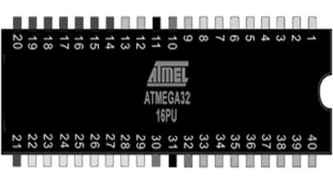
The ATMega32 is a high-performance, low-power Microchip 8-bit AVR® RISC-based microcontroller that combines 32 KB ISP flash memory with 1 KB EEPROM, 2 KB SRAM, 54/69 general purpose I/O lines, 32 general purpose working registers, three flexible timer/counters with compare modes, internal and external interrupts, serial programmable USART, an 8-channel 10-bit A/D converter, programmable watchdog timer with internal oscillator, SPI serial port, and five software selectable power saving modes. The device operates between 1.8-5.5 volts. This makes it suitable as external rom for boot and serial and I/O device for retro microprocessors like the Z80. The ATMega32 is used in a lot of MBC (Minimal Computer Board) designs like the Z80 MBC.

The Arduino Mega is a big Arduino board based on the ATmega2560. It has 256 KB of Flash Memory ( 8 KB used by bootloader), 8 KB Sram and 4 KB Eeprom, 54 digital input/output pins, 16 analog inputs, 4 UARTs (hardware serial ports) and a 16 MHz crystal oscillator. This makes it perfect to emulate Rom / Ram and I/O for a lot of old 8bit microprocessors. There are a lot of so called Retroshields for a wide verity of 8 bit processors like the Z80, the 6502, the 1802, the 2605 and 68xx processors. Sometimes even a small system using basic or emulation of an old computer is available in open source.
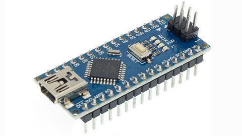
The Ardiono Uno and the Arduino Nano are often used as basic boards for chip testers, ISP programmers and f.i. as serial interface on a Retro computer where these boards replace a lot of glue logic. On the Apple1 replica the Arduino Nano replaces the terminal interface emulating the keyboard and the CRT interface. I also sell a dram tester based on Arduino Uno or Arduino Nano boards.

In retro designs the AVR chips are very handy to replace a lot of glue logic and I/O devices, because the AVR chips and boards support SPI they can easily interface to cheap SD card disk drives and realtime clock boards. So even if these chips are not retro themselves, the are often used in combination with Retro computers.
Have fun, regards, Hein Pragt.
Atmega328 retro board

Sometimes you have a project that you started and did not finish that keeps staring you in the eye every time you enter your shack. This was one of mine, I was planning to build a copy of the famous MPF1 board, but after soldering the keys and the displays, it stopped. After a while the urge of building a copy of the MPF1 faded and the board was laying on my desk. Then I thought about creating an ATMega328 based universal retro board that I could use to emulate f.i. a KIM1 or even a MPF1. The problem was the amount of I/O pins an ATMega328 has when using an external oscillator. But with some deep thinking and some clever design I managed to fit it all on one ATMega328 and keeping the RX/TX pins free for serial communication for debugging messages. This is the design I came up with.

I use two common cathode seven segment X 4 displays and I driver them using an ULN2803 that contains 8 Darlington transistor circuits. The outputs drive the displays (active to ground) but also the scanlines of the keyboard. As I wanted nine rows (MPF1) I had to use a clever trick, there is a 9e state and that is “all off”. By connecting the last row to the ground I can read these pins if all scanlines are inactive. The last button is hardwired to the reset pin. Furthermore the design is very straightforward, the TX line is used as an output for a scanline so it can be used as serial out at the same time. Only the first display will light up a little extra. The RX pin is left free so this can also be used.
The design is made in a way that the ATMega328 chip can be easily replaced with an Arduino Uno, that makes development very easy as you can download the sketch from the IDE and monitor using the terminal of the IDE. When all is working fine, just program the code in an ATMega328 and put the chip in place. Here I have a zip file with the basic test code to see if the hardware is working and an example of the keyboard and display drivers code.

When everything was working I took the sourcecode of the KIMUNO project and cleaned up the code and added my own keyboard and display drivers. This took me a while because the code was a little unclear sometimes. I reformatted / restuctured the code, deleted some unused code and added comment. After a few evening the KIM1 clone was working on my hardware. At the end of the page I included my full sourcecode of the project. And after putting the code inside a standalone ATMega328, this was the result. A working KIM1 emulator.

I hope I have inspired someone to build this and even add more features or other emulations. I still want to write a full MPF1 emulation for this board, but that is one of the future plans.
Sourecode KIM1 ATMega328
Have fun, regards, Hein Pragt.
Arduino Uno ATMega328 pins
The Arduino Uno is not a very Retro style board but it is one of the boards that made microcontrollers available for the main public with a simple and free IDE and opensource hardware. I like using the AVR chips and nowadays a lot new designs of old retro computers contain an AVR chip to replace al lot of glue logic chips. There are even complete emulations of old system available on AVR chips and f.i. de KIM-Uno is a complete emulation of the very old KIM computer board on an Arduino Uno.
AVR is a family of microcontrollers developed since 1996 by Atmel and these are modified Harvard architecture 8-bit RISC single-chip microcontrollers. AVR was one of the first microcontroller families to use on-chip flash memory for program storage. The AVR architecture was conceived by two students at the Norwegian Institute of Technology (NTH) Alf-Egil Bogen and Vegard Wollan. Atmel says that the name AVR is not an acronym and does not stand for anything in particular. However, it is commonly accepted that AVR stands for Alf and Vegard’s RISC processor. The AVR 8-bit microcontroller architecture was introduced in 1997.
In 2009 the team that would become Arduino was formed with the idea of an accessible, affordable electronics development platform. This would eventually give birth to the Arduino UNO. That cheap little board went all over the world and one of oy successors was the Arduino Nano, that us internally the same but has a much smaller size. It isvery easy to use the ATMega328 (DIL version 28 pins) in an electronic design as standalone microcontroller and because it has build in flash and sram memory, 20 I/O pins and a lot of internal peripherals (like a build in UART) it can be used in all kinds of remakes of old computer designs.
When I develop I like to use an UNO or Nano as a drop in for the ATMega328 chip, here is the mapping of the Arduino Uno to the ATMega328 pins.

The same for the Arduino Nano, this board has the 32 pins atmega328 chip.

Have fun, regards, Hein Pragt.
Eight digit seven segment display

When you want to clone a retro computer board like the MK14 or KIM you will need to connect a seven segment display array. This may also be very nice if you design your own standalone mini computer board. I was experimenting with a Tang Nano FPGA and also needed a display and that is when I decided to document what I made. This is a simple universal 8 digit seven segment display unit that can be driven by 8 (or 7) segment select lines and 8 row select lines. The idea is that you can multiplex the displays, so first select display 1 and output the correct segments, then select display 2 and output the correct segments and so on. If you do this at a speed of more then 50 times a second it will appear that all displays are stable and continuously displaying. This is a basic design you can use in your designs.

I use two 4 digit seven segments display units with common cathode (-) lines, but you can also use single or even 8 digit displays. You can also use 7 digits, in this case you will only connect the first 6 row select lines. To select a display we need a kind of switch, most MCU (or FPGA) chips are not capable of driving this current so we need a transistor to switch the display on or off. But I like the very handy, cheap and common Darlington-array ULN 2803 chip that is perfect for this job. The segements are drivern with a positive voltage for on and the rows als also selected with a positive level. You can use this design for 5V and also for 3V3 designs without any modification.

In the segment lines we need some way to reduce the current for the leds in out display and 470 Ohm is a very common value. You can lower or raise this value a little to make the displays light up brighter as you like. The ULN2803 is also very easy to wire on a breadboard, all the inputs are on one side and all the outputs on the other side, and compared to 8 transistors with a base resistor this chip takes up very little space.
Have fun, regards, Hein Pragt.
TTL IC Overview

This is a table with an overview of all TTL IC typenumbers and a short description of the chip. The chips are available in many variants such as LS and HC types, the operation is the same, but the electrical specifications are different. You cannot simply replace an LS with an HC type without being sure that the fan-in and fan-out and the threshold values have no effect.
List of TTL IC’s
| Part number | Description |
|---|---|
| 7400 | quad 2-input NAND gate |
| 7401 | quad 2-input NAND gate with open collector outputs |
| 7402 | quad 2-input NOR gate |
| 7403 | quad 2-input NAND gate with open collector outputs |
| 7404 | hex inverter |
| 7405 | hex inverter with open collector outputs |
| 7406 | hex inverter buffer/driver with 30 V open collector outputs |
| 7407 | hex buffer/driver with 30 V open collector outputs |
| 7408 | quad 2-input AND gate |
| 7409 | quad 2-input AND gate with open collector outputs |
| 7410 | triple 3-input NAND gate |
| 7411 | triple 3-input AND gate |
| 7412 | triple 3-input NAND gate with open collector outputs |
| 7413 | dual Schmitt trigger 4-input NAND gate |
| 7414 | hex Schmitt trigger inverter |
| 7415 | triple 3-input AND gate with open collector outputs |
| 7416 | hex inverter buffer/driver with 15 V open collector outputs |
| 7417 | hex buffer/driver with 15 V open collector outputs |
| 7418 | dual 4-input NAND gate with Schmitt trigger inputs |
| 7419 | hex Schmitt trigger inverter |
| 7420 | dual 4-input NAND gate |
| 7421 | dual 4-input AND gate |
| 7422 | dual 4-input NAND gate with open collector outputs |
| 7423 | expandable dual 4-input NOR gate with strobe |
| 7424 | quad 2-input NAND gate gates with schmitt-trigger line-receiver inputs. |
| 7425 | dual 4-input NOR gate with strobe |
| 7426 | quad 2-input NAND gate with 15 V open collector outputs |
| 7427 | triple 3-input NOR gate |
| 7428 | quad 2-input NOR buffer |
| 7430 | 8-input NAND gate |
| 7431 | hex delay elements |
| 7432 | quad 2-input OR gate |
| 7433 | quad 2-input NOR buffer with open collector outputs |
| 7434 | hex noninverters |
| 7435 | hex noninverters with open-collector outputs |
| 7436 | quad 2-input NOR gate (different pinout than 7402) |
| 7437 | quad 2-input NAND buffer |
| 7438 | quad 2-input NAND buffer with open collector outputs |
| 7439 | quad 2-input NAND buffer with open collector outputs, input and output terminals flipped, otherwise functionally identical to 7438 |
| 7440 | dual 4-input NAND buffer |
| 7441 | BCD to decimal decoder/Nixie tube driver |
| 7442 | BCD to decimal decoder |
| 7443 | excess-3 to decimal decoder |
| 7444 | excess-3-Gray code to decimal decoder |
| 7445 | BCD to decimal decoder/driver |
| 7446 | BCD to seven-segment display decoder/driver with 30 V open collector outputs |
| 7447 | BCD to 7-segment decoder/driver with 15 V open collector outputs |
| 7448 | BCD to 7-segment decoder/driver with Internal Pullups |
| 7449 | BCD to 7-segment decoder/driver with open collector outputs |
| 7450 | dual 2-wide 2-input AND-OR-invert gate (one gate expandable) |
| 7451 | dual 2-wide 2-input AND-OR-invert gate |
| 7452 | expandable 4-wide 2-input AND-OR gate |
| 7453 | expandable 4-wide 2-input AND-OR-invert gate |
| 7454 | 3-2-2-3-input AND-OR-invert gate |
| 7455 | 2-wide 4-input AND-OR-invert Gate (74H version is expandable) |
| 7456 | 50:1 frequency divider |
| 7457 | 60:1 frequency divider |
| 7458 | 2-input & 3-input AND-OR Gate |
| 7459 | 2-input & 3-input AND-OR-invert Gate |
| 7460 | dual 4-input expander |
| 7461 | triple 3-input expander |
| 7462 | 3-2-2-3-input AND-OR expander |
| 7463 | hex current sensing interface gates |
| 7464 | 4-2-3-2-input AND-OR-invert gate |
| 7465 | 4-2-3-2 input AND-OR-invert gate with open collector output |
| 7468 | dual 4 bit decade counters |
| 7469 | dual 4 bit binary counters |
| 7470 | AND-gated positive edge triggered J-K flip-flop with preset and clear |
| 7471 | AND-or-gated J-K master-slave flip-flop with preset |
| 7472 | AND gated J-K master-slave flip-flop with preset and clear |
| 7473 | dual J-K flip-flop with clear |
| 7474 | dual D positive edge triggered flip-flop with preset and clear |
| 7475 | 4-bit bistable latch |
| 7476 | dual J-K flip-flop with preset and clear |
| 7477 | 4-bit bistable latch |
| 7478 | dual positive pulse triggered J-K flip-flop with preset, common clock, and common clear |
| 7479 | dual D flip-flop |
| 7480 | gated full adder |
| 7481 | 16-bit random access memory |
| 7482 | 2-bit binary full adder |
| 7483 | 4-bit binary full adder |
| 7484 | 16-bit random access memory |
| 7485 | 4-bit magnitude comparator |
| 7486 | quad 2-input XOR gate |
| 7487 | 4-bit true/complement/zero/one element |
| 7488 | 256-bit read-only memory |
| 7489 | 64-bit random access memory |
| 7490 | decade counter (separate divide-by-2 and divide-by-5 sections) |
| 7491 | 8-bit shift register, serial In, serial out, gated input |
| 7492 | divide-by-12 counter (separate divide-by-2 and divide-by-6 sections) |
| 7493 | 4-bit binary counter (separate divide-by-2 and divide-by-8 sections) |
| 7494 | 4-bit shift register, dual asynchronous presets |
| 7495 | 4-bit shift register, parallel In, parallel out, serial input |
| 7496 | 5-bit parallel-In/parallel-out shift register, asynchronous preset |
| 7497 | synchronous 6-bit binary rate multiplier |
| 7498 | 4-bit data selector/storage register |
| 7499 | 4-bit bidirectional universal shift register |
| 74100 | dual 4-bit bistable latch |
| 74101 | AND-OR-gated J-K negative-edge-triggered flip-flop with preset |
| 74102 | AND-gated J-K negative-edge-triggered flip-flop with preset and clear |
| 74103 | dual J-K negative-edge-triggered flip-flop with clear |
| 74104 | J-K master-slave flip-flop |
| 74105 | J-K master-slave flip-flop |
| 74106 | dual J-K negative-edge-triggered flip-flop with preset and clear |
| 74107 | dual J-K flip-flop with clear |
| 74108 | dual J-K negative-edge-triggered flip-flop with preset, common clear, and common clock |
| 74109 | dual J-Not-K positive-edge-triggered flip-flop with clear and preset |
| 74110 | AND-gated J-K master-slave flip-flop with data lockout |
| 74111 | dual J-K master-slave flip-flop with data lockout |
| 74112 | dual J-K negative-edge-triggered flip-flop with clear and preset |
| 74113 | dual J-K negative-edge-triggered flip-flop with preset |
| 74114 | dual J-K negative-edge-triggered flip-flop with preset, common clock and clear |
| 74116 | dual 4-bit latch with clear |
| 74118 | hex set/reset latch |
| 74119 | hex set/reset latch |
| 74120 | dual pulse synchronizer/drivers |
| 74121 | monostable multivibrator |
| 74122 | retriggerable monostable multivibrator with clear |
| 74123 | dual retriggerable monostable multivibrator with clear |
| 74124 | dual voltage-controlled oscillator |
| 74125 | quad bus buffer with three-state outputs, negative enable |
| 74126 | quad bus buffer with three-state outputs, positive enable |
| 74128 | quad 2-input NOR Line driver |
| 74130 | quad 2-input AND gate buffer with 30 V open collector outputs |
| 74131 | quad 2-input AND gate buffer with 15 V open collector outputs |
| 74132 | quad 2-input NAND schmitt trigger |
| 74133 | 13-input NAND gate |
| 74134 | 12-input NAND gate with three-state output |
| 74135 | quad exclusive-or/NOR gate |
| 74136 | quad 2-input XOR gate with open collector outputs |
| 74137 | 3 to 8-line decoder/demultiplexer with address latch |
| 74138 | 3 to 8-line decoder/demultiplexer |
| 74139 | dual 2 to 4-line decoder/demultiplexer |
| 74140 | dual 4-input NAND line driver |
| 74141 | BCD to decimal decoder/driver for cold-cathode indicator/Nixie tube |
| 74142 | decade counter/latch/decoder/driver for Nixie tubes |
| 74143 | decade counter/latch/decoder/7-segment driver, 15 ma constant current |
| 74144 | decade counter/latch/decoder/7-segment driver, 15 V open collector outputs |
| 74145 | BCD to decimal decoder/driver |
| 74147 | 10-line to 4-line priority encoder |
| 74148 | 8-line to 3-line priority encoder |
| 74150 | 16-line to 1-line data selector/multiplexer |
| 74151 | 8-line to 1-line data selector/multiplexer |
| 74152 | 8-line to 1-line data selector/multiplexer |
| 74153 | dual 4-line to 1-line data selector/multiplexer |
| 74154 | 4-line to 16-line decoder/demultiplexer |
| 74155 | dual 2-line to 4-line decoder/demultiplexer |
| 74156 | dual 2-line to 4-line decoder/demultiplexer with open collector outputs |
| 74157 | quad 2-line to 1-line data selector/multiplexer, noninverting |
| 74158 | quad 2-line to 1-line data selector/multiplexer, inverting |
| 74159 | 4-line to 16-line decoder/demultiplexer with open collector outputs |
| 74160 | synchronous 4-bit decade counter with asynchronous clear |
| 74161 | synchronous 4-bit binary counter with asynchronous clear |
| 74162 | synchronous 4-bit decade counter with synchronous clear |
| 74163 | synchronous 4-bit binary counter with synchronous clear |
| 74164 | 8-bit parallel-out serial shift register with asynchronous clear |
| 74165 | 8-bit serial shift register, parallel Load, complementary outputs |
| 74166 | parallel-Load 8-bit shift register |
| 74167 | synchronous decade rate multiplier |
| 74168 | synchronous 4-bit up/down decade counter |
| 74169 | synchronous 4-bit up/down binary counter |
| 74170 | 4 by 4 register file with open collector outputs |
| 74171 | quad D-type flip-flops with clear |
| 74172 | 16-bit multiple port register file with three-state outputs |
| 74173 | quad d flip-flop with three-state outputs |
| 74174 | hex d flip-flop with common clear |
| 74175 | quad d edge-triggered flip-flop with complementary outputs and asynchronous clear |
| 74176 | presettable decade (bi-quinary) counter/latch |
| 74177 | presettable binary counter/latch |
| 74178 | 4-bit parallel-access shift register |
| 74179 | 4-bit parallel-access shift register with asynchronous clear and complementary Qd outputs |
| 74180 | 9-bit odd/even parity bit generator and checker |
| 74181 | 4-bit arithmetic logic unit and function generator |
| 74182 | lookahead carry generator |
| 74183 | dual carry-save full adder |
| 74184 | BCD to binary converter |
| 74185 | 6-bit binary to BCD converter |
| 74186 | 512-bit (64×8) read-only memory with open collector outputs |
| 74187 | 1024-bit (256×4) read only memory with open collector outputs |
| 74188 | 256-bit (32×8) programmable read-only memory with open collector outputs |
| 74189 | 64-bit (16×4) RAM with inverting three-state outputs |
| 74190 | synchronous up/down decade counter |
| 74191 | synchronous up/down binary counter |
| 74192 | synchronous up/down decade counter with clear |
| 74193 | synchronous up/down 4-bit binary counter with clear |
| 74194 | 4-bit bidirectional universal shift register |
| 74195 | 4-bit parallel-access shift register |
| 74196 | presettable decade counter/latch |
| 74197 | presettable binary counter/latch |
| 74198 | 8-bit bidirectional universal shift register |
| 74199 | 8-bit bidirectional universal shift register with J-Not-K serial inputs |
| 74200 | 256-bit ram with three-state outputs |
| 74201 | 256-bit (256×1) ram with three-state outputs |
| 74206 | 256-bit ram with open collector outputs |
| 74209 | 1024-bit (1024×1) ram with three-state output |
| 74210 | octal buffer |
| 74219 | 64-bit (16×4) RAM with noninverting three-state outputs |
| 74221 | dual monostable multivibrator with schmitt trigger input |
| 74222 | 16 by 4 synchronous FIFO memory with three-state outputs |
| 74224 | 16 by 4 synchronous FIFO memory with three-state outputs |
| 74225 | asynchronous 16×5 FIFO memory |
| 74226 | 4-bit parallel latched bus transceiver with three-state outputs |
| 74227 | 64-bit fifo memories 16×4 |
| 74228 | 64-bit fifo memories 16×4 open-collector outputs |
| 74230 | octal buffer/driver with three-state outputs, true and complementary inputs |
| 74231 | octal buffer and line driver with three-state outputs, G and /G complementary inputs |
| 74232 | quad NOR Schmitt trigger |
| 74237 | 3-of-8 decoder/demultiplexer with address latch, active high outputs |
| 74238 | 3-of-8 decoder/demultiplexer, active high outputs |
| 74239 | dual 2-of-4 decoder/demultiplexer, active high outputs |
| 74240 | octal buffer with Inverted three-state outputs |
| 74241 | octal buffer with noninverted three-state outputs |
| 74242 | quad bus transceiver with Inverted three-state outputs |
| 74243 | quad bus transceiver with noninverted three-state outputs |
| 74244 | octal buffer with noninverted three-state outputs |
| 74245 | octal bus transceiver with noninverted three-state outputs |
| 74246 | BCD to 7-segment decoder/driver with 30 V open collector outputs |
| 74247 | BCD to 7-segment decoder/driver with 15 V open collector outputs |
| 74248 | BCD to 7-segment decoder/driver with Internal Pull-up outputs |
| 74249 | BCD to 7-segment decoder/driver with open collector outputs |
| 74250 | 1 of 16 data selectors/multiplexers |
| 74251 | 8-line to 1-line data selector/multiplexer with complementary three-state outputs |
| 74253 | dual 4-line to 1-line data selector/multiplexer with three-state outputs |
| 74255 | dual 4-bit addressable latch |
| 74256 | dual 4-bit addressable latch |
| 74257 | quad 2-line to 1-line data selector/multiplexer with noninverted three-state outputs |
| 74258 | quad 2-line to 1-line data selector/multiplexer with Inverted three-state outputs |
| 74259 | 8-bit addressable latch |
| 74260 | dual 5-input NOR gate |
| 74261 | 2-bit by 4-bit parallel binary multiplier |
| 74264 | look ahead carry generator |
| 74265 | quad complementary output elements |
| 74266 | quad 2-input XNOR gate with open collector outputs |
| 74268 | hex d-type latches three-state outputs, common output control, common enable |
| 74270 | 2048-bit (512×4) read only memory with open collector outputs |
| 74271 | 2048-bit (256×8) read only memory with open collector outputs |
| 74273 | 8-bit register with reset |
| 74274 | 4-bit by 4-bit binary multiplier |
| 74275 | 7-bit slice Wallace tree |
| 74276 | quad J-Not-K edge-triggered Flip-Flops with separate clocks, common preset and clear |
| 74278 | 4-bit cascadeable priority registers with latched data inputs |
| 74279 | quad set-reset latch |
| 74280 | 9-bit odd/even Parity bit Generator/checker |
| 74281 | 4-bit parallel binary accumulator |
| 74282 | look-ahead carry generator with selectable carry inputs |
| 74283 | 4-bit binary Full adder |
| 74284 | 4-bit by 4-bit parallel binary multiplier (low order 4 bits of product) |
| 74285 | 4-bit by 4-bit parallel binary multiplier (high order 4 bits of product) |
| 74286 | 9-bit parity generator/checker with bus driver parity I/O port |
| 74287 | 1024-bit (256×4) programmable read-only memory with three-state outputs |
| 74288 | 256-bit (32×8) programmable read-only memory with three-state outputs |
| 74289 | 64-bit (16×4) RAM with open collector outputs |
| 74290 | decade counter (separate divide-by-2 and divide-by-5 sections) |
| 74291 | 4-bit universal shift register, binary up/down counter, synchronous |
| 74292 | programmable frequency divider/digital timer |
| 74293 | 4-bit binary counter (separate divide-by-2 and divide-by-8 sections) |
| 74294 | programmable frequency divider/digital timer |
| 74295 | 4-bit bidirectional register with three-state outputs |
| 74297 | digital phase-locked-loop filter |
| 74298 | quad 2-input multiplexer with storage |
| 74299 | 8-bit bidirectional universal shift/storage register with three-state outputs |
| 74301 | 256-bit (256×1) random access memory with open collector output |
| 74309 | 1024-bit (1024×1) random access memory with open collector output |
| 74310 | octal buffer with Schmitt trigger inputs |
| 74314 | 1024-bit random access memory |
| 74319 | 64-bit random access memories 16×4 open collector outputs |
| 74320 | crystal controlled oscillator |
| 74321 | crystal-controlled oscillators with F/2 and F/4 count-down outputs |
| 74322 | 8-bit shift register with sign extend, three-state outputs |
| 74323 | 8-bit bidirectional universal shift/storage register with three-state outputs |
| 74324 | voltage controlled oscillator (or crystal controlled) |
| 74340 | octal buffer with Schmitt trigger inputs and three-state inverted outputs |
| 74341 | octal buffer with Schmitt trigger inputs and three-state noninverted outputs |
| 74344 | octal buffer with Schmitt trigger inputs and three-state noninverted outputs |
| 74347 | bcd to seven segment decoders/drivers open collector outputs, low voltage version of 7447 |
| 74348 | 8 to 3-line priority encoder with three-state outputs |
| 74350 | 4-bit shifter with three-state outputs |
| 74351 | dual 8-line to 1-line data selectors/multiplexers with three-state outputs and 4 common data inputs |
| 74352 | dual 4-line to 1-line data selectors/multiplexers with inverting outputs |
| 74353 | dual 4-line to 1-line data selectors/multiplexers with inverting three-state outputs |
| 74354 | 8 to 1-line data selector/multiplexer with transparent latch, three-state outputs |
| 74355 | 8-line to 1-line data selector/multiplexer with transparent registers, open-collector outputs |
| 74356 | 8 to 1-line data selector/multiplexer with edge-triggered register, three-state outputs |
| 74357 | 8-line to 1-line data selectors/multiplexers/edge-triggered registers, open-collector outputs |
| 74361 | bubble memory function timing generator |
| 74362 | four-phase clock generator/driver |
| 74363 | octal three-state D-latches |
| 74365 | hex buffer with noninverted three-state outputs |
| 74366 | hex buffer with Inverted three-state outputs |
| 74367 | hex buffer with noninverted three-state outputs |
| 74368 | hex buffer with Inverted three-state outputs |
| 74370 | 2048-bit (512×4) read-only memory with three-state outputs |
| 74371 | 2048-bit (256×8) read-only memory with three-state outputs |
| 74373 | octal transparent latch with three-state outputs |
| 74374 | octal register with three-state outputs |
| 74375 | quad bistable latch |
| 74376 | quad J-Not-K flip-flop with common clock and common clear |
| 74377 | 8-bit register with clock enable |
| 74378 | 6-bit register with clock enable |
| 74379 | 4-bit register with clock enable and complementary outputs |
| 74380 | 8-bit multifunction register |
| 74381 | 4-bit arithmetic logic unit/function generator with generate and propagate outputs |
| 74382 | 4-bit arithmetic logic unit/function generator with ripple carry and overflow outputs |
| 74384 | 8-bit by 1-bit two’s complement multipliers |
| 74385 | quad 4-bit adder/subtractor |
| 74386 | quad 2-input XOR gate |
| 74387 | 1024-bit (256×4) programmable read-only memory with open collector outputs |
| 74388 | 4-bit register with standard and three-state outputs |
| 74390 | dual 4-bit decade counter |
| 74393 | dual 4-bit binary counter |
| 74395 | 4-bit universal shift register with three-state outputs |
| 74396 | octal storage registers, parallel access |
| 74398 | quad 2-input multiplexers with storage and complementary outputs |
| 74399 | quad 2-input multiplexer with storage |
| 74405 | 1 to 8 decoder, equivalent to Intel 8205, only found as UCY74S405 so might be non-TI number |
| 74408 | 8-bit parity tree |
| 74412 | multi-mode buffered 8-bit latches with three-state outputs and clear |
| 74422 | re-triggerable mono-stable multivibrators, two inputs |
| 74423 | dual retriggerable monostable multivibrator |
| 74424 | two-phase clock generator/driver |
| 74425 | quad gates with three-state outputs and active low enables |
| 74426 | quad gates with three-state outputs and active high enables |
| 74428 | system controller for 8080a |
| 74436 | line driver/memory driver circuits – mos memory interface, damping output resistor |
| 74437 | line driver/memory driver circuits – mos memory interface |
| 74438 | system controller for 8080a |
| 74440 | quad tridirectional bus transceiver with noninverted open collector outputs |
| 74441 | quad tridirectional bus transceiver with Inverted open collector outputs |
| 74442 | quad tridirectional bus transceiver with noninverted three-state outputs |
| 74443 | quad tridirectional bus transceiver with Inverted three-state outputs |
| 74444 | quad tridirectional bus transceiver with Inverted and noninverted three-state outputs |
| 74445 | bcd-to-decimal decoders/drivers |
| 74446 | quad bus transceivers with direction controls |
| 74447 | bcd-to-seven-segment decoders/drivers, low voltage version of 74247 |
| 74448 | quad tridirectional bus transceiver with Inverted and noninverted open collector outputs |
| 74449 | quad bus transceivers with direction controls, true outputs |
| 74450 | 16-to-1 multiplexer with complementary outputs |
| 74451 | dual 8-to-1 multiplexer |
| 74452 | dual decade counter, synchronous |
| 74453 | dual binary counter, synchronous |
| 74453 | quad 4-to-1 multiplexer |
| 74454 | dual decade up/down counter, synchronous, preset input |
| 74455 | dual binary up/down counter, synchronous, preset input |
| 74456 | NBCD (Natural binary coded decimal) adder |
| 74460 | bus transfer switch |
| 74461 | 8-bit presettable binary counter with three-state outputs |
| 74462 | fiber-optic link transmitter |
| 74463 | fiber-optic link receiver |
| 74465 | octal buffer with three-state true outputs |
| 74466 | octal buffers with three-state inverted outputs |
| 74467 | octal buffers with three-state true outputs |
| 74468 | octal buffers with three-state inverted outputs |
| 74470 | 2048-bit (256×8) programmable read-only memory with open collector outputs |
| 74471 | 2048-bit (256×8) programmable read-only memory with three-state outputs |
| 74472 | programmable read-only memory with open collector outputs |
| 74473 | programmable read-only memory with three-state outputs |
| 74474 | programmable read-only memory with open collector outputs |
| 74475 | programmable read-only memory with three-state outputs |
| 74481 | 4-bit slice cascadable processor elements |
| 74482 | 4-bit slice expandable control elements |
| 74484 | BCD-to-binary converter |
| 74485 | binary-to-BCD converter |
| 74490 | dual decade counter |
| 74491 | 10-bit binary up/down counter with limited preset and three-state outputs |
| 74498 | 8-bit bidirectional shift register with parallel inputs and three-state outputs |
| 74508 | 8-bit multiplier/divider |
| 74518 | 8-bit comparator with open collector output, input pull-up resistor |
| 74519 | 8-bit comparator with open collector output |
| 74520 | 8-bit comparator with inverted totem-pole output, input pull-up resistor |
| 74521 | 8-bit comparator with inverted totem-pole output |
| 74522 | 8-bit comparator with inverted open-collector output, input pull-up resistor |
| 74526 | fuse programmable identity comparator, 16 bit |
| 74527 | fuse programmable identity comparator, 8 bit + 4 bit conventional Identity comparator |
| 74528 | fuse programmable Identity comparator, 12 bit |
| 74531 | octal transparent latch with 32 ma three-state outputs |
| 74532 | octal register with 32 ma three-state outputs |
| 74533 | octal transparent latch with inverting three-state outputs |
| 74534 | octal register with inverting three-state outputs |
| 74535 | octal transparent latch with inverting three-state outputs |
| 74536 | octal register with inverting 32 ma three-state outputs |
| 74537 | BCD to decimal decoder with three-state outputs |
| 74538 | 1 of 8 decoder with three-state outputs |
| 74539 | dual 1 of 4 decoder with three-state outputs |
| 74540 | inverting octal buffer with three-state outputs |
| 74541 | non-inverting octal buffer with three-state outputs |
| 74544 | non-inverting octal registered transceiver with three-state outputs |
| 74558 | 8-bit by 8-bit multiplier with three-state outputs |
| 74560 | 4-bit decade counter with three-state outputs |
| 74561 | 4-bit binary counter with three-state outputs |
| 74563 | 8-bit d-type transparent latch with inverting three-state outputs |
| 74564 | 8-bit d-type edge-triggered register with inverting three-state outputs |
| 74568 | decade up/down counter with three-state outputs |
| 74569 | binary up/down counter with three-state outputs |
| 74573 | octal D-type transparent latch with three-state outputs |
| 74574 | octal D-type edge-triggered flip-flop with three-state outputs |
| 74575 | octal D-type flip-flop with synchronous clear, three-state outputs |
| 74576 | octal D-type flip-flop with inverting three-state outputs |
| 74577 | octal D-type flip-flop with synchronous clear, inverting three-state outputs |
| 74580 | octal transceiver/latch with inverting three-state outputs |
| 74589 | 8-bit shift register with input latch, three-state outputs |
| 74590 | 8-bit binary counter with output registers and three-state outputs |
| 74591 | 8-bit binary counters with output registers, open-collector outputs |
| 74592 | 8-bit binary counter with input registers |
| 74593 | 8-bit binary counter with input registers and three-state outputs |
| 74594 | 8-bit shift registers with output latches |
| 74595 | 8-bit shift registers with output latches, three-state parallel outputs |
| 74596 | 8-bit shift registers with output latches, open-collector parallel outputs |
| 74597 | 8-bit shift registers with input latches |
| 74598 | 8-bit shift register with input latches |
| 74599 | 8-bit shift registers with output latches, open-collector outputs |
| 74600 | dynamic memory refresh controller, transparent and burst modes, for 4K or 16K drams |
| 74601 | dynamic memory refresh controller, transparent and burst modes, for 64K drams |
| 74602 | dynamic memory refresh controller, cycle steal and burst modes, for 4K or 16K drams |
| 74603 | dynamic memory refresh controller, cycle steal and burst modes, for 64K drams |
| 74604 | octal 2-input multiplexer with latch, high-speed, with three-state outputs |
| 74605 | latch, high-speed, with open collector outputs |
| 74606 | octal 2-input multiplexer with latch, glitch-free, with three-state outputs |
| 74607 | octal 2-input multiplexer with latch, glitch-free, with open collector outputs |
| 74608 | memory cycle controller |
| 74610 | memory mapper, latched, three-state outputs |
| 74611 | memory mapper, latched, open collector outputs |
| 74612 | memory mapper, three-state outputs |
| 74613 | memory mapper, open collector outputs |
| 74618 | Schmitt-trigger positive-nand gates with totem-pole outputs |
| 74619 | Schmitt-trigger inverters with totem-pole outputs |
| 74620 | octal bus transceiver, inverting, three-state outputs |
| 74621 | octal bus transceiver, noninverting, open collector outputs |
| 74622 | octal bus transceiver, inverting, open collector outputs |
| 74623 | octal bus transceiver, noninverting, three-state outputs |
| 74624 | voltage-controlled oscillator with enable control, range control, two-phase outputs |
| 74625 | dual voltage-controlled oscillator with two-phase outputs |
| 74626 | dual voltage-controlled oscillator with enable control, two-phase outputs |
| 74627 | dual voltage-controlled oscillator |
| 74628 | voltage-controlled oscillator with enable control, range control, external temperature compensation, and two-phase outputs |
| 74629 | dual voltage-controlled oscillator with enable control, range control |
| 74630 | 16-bit error detection and correction (EDAC) with three-state outputs |
| 74631 | 16-bit error detection and correction with open collector outputs |
| 74632 | 32-bit parallel error detection and correction, three-state outputs, byte-write |
| 74633 | 32-bit parallel error detection and correction, open-collector outputs, byte-write |
| 74634 | 32-bit parallel error detection and correction, three-state outputs |
| 74635 | 32-bit parallel error detection and correction, open-collector outputs |
| 74638 | octal bus transceiver with inverting three-state outputs |
| 74639 | octal bus transceiver with noninverting three-state outputs |
| 74640 | octal bus transceiver with inverting three-state outputs |
| 74641 | octal bus transceiver with noninverting open collector outputs |
| 74642 | octal bus transceiver with inverting open collector outputs |
| 74643 | octal bus transceiver with mix of inverting and noninverting three-state outputs |
| 74644 | octal bus transceiver with mix of inverting and noninverting open collector outputs |
| 74645 | octal bus transceiver |
| 74646 | octal bus transceiver/latch/multiplexer with noninverting three-state outputs |
| 74647 | octal bus transceiver/latch/multiplexer with noninverting open collector outputs |
| 74648 | octal bus transceiver/latch/multiplexer with inverting three-state outputs |
| 74649 | octal bus transceiver/latch/multiplexer with inverting open collector outputs |
| 74651 | octal bus transceiver/register with inverting three-state outputs |
| 74652 | octal bus transceiver/register with noninverting three-state outputs |
| 74653 | octal bus transceiver/register with inverting three-state and open collector outputs |
| 74654 | octal bus transceiver/register with noninverting three-state and open collector outputs |
| 74658 | octal bus transceiver with Parity, inverting |
| 74659 | octal bus transceiver with Parity, noninverting |
| 74664 | octal bus transceiver with Parity, inverting |
| 74665 | octal bus transceiver with Parity, noninverting |
| 74668 | synchronous 4-bit decade Up/down counter |
| 74669 | synchronous 4-bit binary Up/down counter |
| 74670 | 4 by 4 register File with three-state outputs |
| 74671 | 4-bit bidirectional shift register/latch /multiplexer with three-state outputs |
| 74672 | 4-bit bidirectional shift register/latch/multiplexer with three-state outputs |
| 74673 | 16-bit serial-in serial-out shift register with output storage registers, three-state outputs |
| 74674 | 16-bit parallel-in serial-out shift register with three-state outputs |
| 74677 | 16-bit address comparator with enable |
| 74678 | 16-bit address comparator with latch |
| 74679 | 12-bit address comparator with latch |
| 74680 | 12-bit address comparator with enable |
| 74681 | 4-bit parallel binary accumulator |
| 74682 | 8-bit magnitude comparator |
| 74683 | 8-bit magnitude comparator with open collector outputs |
| 74684 | 8-bit magnitude comparator |
| 74685 | 8-bit magnitude comparator with open collector outputs |
| 74686 | 8-bit magnitude comparator with enable |
| 74687 | 8-bit magnitude comparator with enable |
| 74688 | 8-bit equality comparator |
| 74689 | 8-bit magnitude comparator with open collector outputs |
| 74690 | three-state outputs |
| 74691 | 4-bit binary counter/latch/multiplexer with asynchronous reset, three-state outputs |
| 74692 | 4-bit decimal counter/latch/multiplexer with synchronous reset, three-state outputs |
| 74693 | 4-bit binary counter/latch/multiplexer with synchronous reset, three-state outputs |
| 74694 | 4-bit decimal counter/latch/multiplexer with synchronous and asynchronous resets, three-state outputs |
| 74695 | 4-bit binary counter/latch/multiplexer with synchronous and asynchronous resets, three-state outputs |
| 74696 | 4-bit decimal counter/register/multiplexer with asynchronous reset, three-state outputs |
| 74697 | 4-bit binary counter/register/multiplexer with asynchronous reset, three-state outputs |
| 74698 | 4-bit decimal counter/register/multiplexer with synchronous reset, three-state outputs |
| 74699 | 4-bit binary counter/register/multiplexer with synchronous reset, three-state outputs |
| 74716 | programmable decade counter |
| 74718 | programmable binary counter |
| 74724 | voltage controlled multivibrator |
| 74740 | octal buffer/Line driver, inverting, three-state outputs |
| 74741 | octal buffer/Line driver, noninverting, three-state outputs, mixed enable polarity |
| 74744 | octal buffer/Line driver, noninverting, three-state outputs |
| 74748 | 8 to 3-line priority encoder |
| 74779 | 8-bit bidirectional binary counter (three-state) |
| 74783 | synchronous address multiplexer |
| 74790 | error detection and correction (EDAC) |
| 74794 | 8-bit register with readback |
| 74795 | octal buffer with three-state outputs |
| 74796 | octal buffer with three-state outputs |
| 74797 | octal buffer with three-state outputs |
| 74798 | octal buffer with three-state outputs |
| 74804 | hex 2-input NAND drivers |
| 74805 | hex 2-input NOR drivers |
| 74808 | hex 2-input AND drivers |
| 74822 | 10-bit bus interface flipflop with three-state outputs |
| 74832 | hex 2-input OR drivers |
| 74848 | 8 to 3-line priority encoder with three-state outputs |
| 74873 | octal transparent latch |
| 74874 | octal d-type flip-flop |
| 74876 | octal d-type flip-flop with inverting outputs |
| 74878 | dual 4-bit d-type flip-flop with synchronous clear, noninverting three-state outputs |
| 74879 | dual 4-bit d-type flip-flop with synchronous clear, inverting three-state outputs |
| 74880 | octal transparent latchwith inverting outputs |
| 74881 | arithmetic logic unit |
| 74882 | 32-bit lookahead carry generator |
| 74888 | 8-bit slice processor |
| 74901 | hex inverting TTL buffer |
| 74902 | hex non-inverting TTL buffer |
| 74903 | hex inverting CMOS buffer |
| 74904 | hex non-inverting CMOS buffer |
| 74905 | 12-Bit successive approximation register |
| 74906 | hex open drain n-channel buffers |
| 74907 | hex open drain p-channel buffers |
| 74908 | dual CMOS 30 V relay driver |
| 74909 | quad voltage comparator |
| 74910 | 256×1 CMOS static RAM |
| 74911 | 4 digit expandable display controller |
| 74912 | 6 digit BCD display controller and driver |
| 74914 | hex schmitt trigger with extended input voltage |
| 74915 | seven segment to BCD decoder |
| 74917 | 6 digit Hex display controller and driver |
| 74918 | dual CMOS 30 V relay driver |
| 74920 | 256×4 CMOS static RAM |
| 74921 | 256×4 CMOS static RAM |
| 74922 | 16-key encoder |
| 74923 | 20-key encoder |
| 74925 | 4-digit counter/display driver |
| 74926 | 4-digit counter/display driver |
| 74927 | 4-digit counter/display driver |
| 74928 | 4-digit counter/display driver |
| 74929 | 1024×1 CMOS static RAM |
| 74930 | 1024×1 CMOS static RAM |
| 74932 | phase comparator |
| 74933 | address bus comparator |
| 74934 | =ADC0829 ADC, see corresponding NSC datasheet |
| 74935 | 3.5-digit digital voltmeter (DVM) support chip for multiplexed 7-segment displays |
| 74936 | 3.75-digit digital voltmeter (DVM) support chip for multiplexed 7-segment displays |
| 74937 | =ADC3511 ADC, see corresponding NSC datasheet |
| 74938 | =ADC3711 ADC, see corresponding NSC datasheet |
| 74941 | octal bus/line drivers/line receivers |
| 74945 | 4 digit up/down counter with decoder and driver |
| 74947 | 4 digit up/down counter with decoder and driver |
| 74948 | =ADC0816 ADC, see corresponding NSC datasheet |
| 74949 | =ADC0808 ADC, see corresponding NSC datasheet |
| 741005 | hex inverting buffer with open-collector output |
| 741035 | hex noninverting buffers with open-collector outputs |
| 742960 | error detection and correction (EDAC) |
| 742961 | edac bus buffer, inverting |
| 742962 | edac bus buffer, noninverting |
| 742968 | dynamic memory controller |
| 742969 | memory timing controller for use with EDAC |
| 742970 | memory timing controller for use without EDAC |
| 744002 | dual 4-input NOR gate |
| 744015 | dual 4-bit shift registers |
| 744016 | quad bilateral switch |
| 744017 | 5-stage ÷10 Johnson counter |
| 744020 | 14-stage binary counter |
| 744024 | 7 stage ripple carry binary counter |
| 744028 | BCD to decimal decoder |
| 744040 | 12-stage binary ripple counter |
| 744046 | phase-locked loop and voltage-controlled oscillator |
| 744049 | hex inverting buffer |
| 744050 | hex buffer/converter (non-inverting) |
| 744051 | high-speed CMOS 8-channel analog multiplexer/demultiplexer |
| 744052 | dual 4-channel analog multiplexer/demultiplexers |
| 744053 | triple 2-channel analog multiplexer/demultiplexers |
| 744059 | programmable divide-by-N counter |
| 744060 | 14-stage binary ripple counter with oscillator |
| 744066 | quad bilateral switches |
| 744067 | 16-channel analog multiplexer/demultiplexer |
| 744075 | triple 3-input OR gate |
| 744078 | 8-input OR/NOR gate |
| 744094 | 8-bit three-state shift register/latch |
| 744316 | quad analog switch |
| 744351 | 8-channel analog multiplexer/demultiplexer with latch |
| 744353 | Triple 2-channel analog multiplexer/demultiplexer with latch |
| 744511 | BCD to 7-segment decoder |
| 744514 | 4-to-16 line decoder/demultiplexer with input latches |
| 744520 | dual 4-bit synchronous binary counter |
| 744538 | dual retriggerable precision monostable multivibrator |
| 747007 | hex buffer |
| 747266 | quad 2-input XNOR gate |
| 7429841 | 10-bit bus-interface D-type latch with three-state outputs |
| 7440103 | presettable 8-bit synchronous down counter |
| 7440105 | 4-bit by 16-word FIFO register |
Programming the ATTiny85

In this post I will explain how to program am ATTiny25/45/85 MCU. I really like the AVR chips, they are powerful, have enough flash and sram memory and have a lot of build in I/O devices. And the chips come in many sizes that all have the same MCU kernel, but a different number of I/O pins and different Flash/Sram sizes. The ATTiny85 is what I use the most, it has the most flash af the 25/45/85 series and it is rather cheap. The chip has 6 programmeble I/O pins and that is enough for a lot of things. It does not have a serial Uart but if you really need this you can use the software Uart. To program this chip you will need a programming environment, I use Visuals Studio PlatformIO and the old but decent Arduino IDE. Fot beginners I would recommend the Arduino IDE as it is foolproof and easier. With PlatformIO you can control much more (like all the fuse settings in binary format) but if you do something wrong you can get totally unusable bricked MCU chips. On this page I describe an Arduino Uno as ISP programmer.
Arduino Uno as ISP
I have bought a lot of Arduino programmers when I first started and I had a lot of problems with them especially the Chinese clones. Then I discovered the Arduino Uno as ISP and build several shields for 8, 14 , 20 and 28 pins AVR chips. Because all the different sizes of chips have their programming pins on different pins and need the power pins also connected, I build several shields. But they are cheap to make. Hier is the schematic of the shield I use for the ATTiny25/45/85 processor.
I use a standard prototype shield and a ZIF header for this (8 pins zif are hard to get so I use a bigger one and put tape on the unused pins), then first upload the Arduino as ISP scketch to the Arduino Uno. Select the AruidnoISP sketch from the examples and select Arduino Uno as board.


Connect the Arduino Uno using the USB cable and select the correct port in the Tools settings. Then use the Upload button to upload the ArduinoISP sketch to the Arduino Uno and your ISP programmer is ready.

I hope this was clear, if you got anything to add to this post then let me know, regards, Hein Pragt.
Programming the ATTiny2313

In this post I will explain how to program am ATTiny2313 / AT90S2313 MCU. I really like the AVR chips, they are powerful, have enough flash and sram memory and have a lot of build in I/O devices. And the chips come in many sizes that all have the same MCU kernel, but a different number of I/O pins and different Flash/Sram sizes. The ATTiny2313 (or the even cheaper AT90S2313) is just in the middle and I like to use this chip and it is not that expensive. To program this chip you will need a programming environment, I use Visuals Studio PlatformIO and the old but decent Arduino IDE. Fot beginners I would recommend the Arduino IDE as it is foolproof and easier. With PlatformIO you can control much more (like all the fuse settings in binary format) but if you do something wrong you can get totally unusable bricked MCU chips. On this page I describe an Arduino Uno as ISP programmer.
Arduino Uno as ISP
I have bought a lot of Arduino programmers when I first started and I had a lot of problems with them especially the Chinese clones. Then I discovered the Arduino Uno as ISP and build several shields for 8, 14 , 20 and 28 pins AVR chips. Because all the different sizes of chips have their programming pins on different pins and need the power pins also connected, I build several shields. But they are cheap to make. Hier is the schematic of the shield I use for the ATTiny2313 / AT90S2313 processor.

I use a standard prototype shield and a ZIF header for this, then first upload the Arduino as ISP scketch to the Arduino Uno. Select the AruidnoISP sketch from the examples and select Arduino Uno as board.
Connect the Arduino Uno using the USB cable and select the correct port in the Tools settings. Then use the Upload button to upload the ArduinoISP sketch to the Arduino Uno and your ISP programmer is ready.
I hope this was clear, if you got anything to add to this post then let me know, regards, Hein Pragt.
Programming the ATMega32A
In this post I will explain how to program am ATMega32A MCU. I really like the AVR chips, they are powerful, have enough flash and sram memory and have a lot of build in I/O devices. And the chips come in many sizes that all have the same MCU kernel, but a different number of I/O pins and different Flash/Sram sizes. If you really need a lot of I/O pins the ATMega32A is what you need, I like to use this chip and it is not that expensive. To program this chip you will need a programming environment, I use Visuals Studio PlatformIO and the old but decent Arduino IDE. Fot beginners I would recommend the Arduino IDE as it is foolproof and easier. With PlatformIO you can control much more (like all the fuse settings in binary format) but if you do something wrong you can get totally unusable bricked MCU chips. On this page I describe the Arduino IDE with an Arduino Uno as ISP programmer.
ARDUINO IDE

I really liked the Arduino IDE until the last versions. The (configuration / libraries) directories it uses are all over your disk and hard to find. That is why I recommend the portable arduino-1.8.19 version. This has all the files in a single directory. Install this version somewhere on your drive and it works out of the box. But out of the box it does not support the ATMega32 processors. There are several solutions that depend on your version of the Arduino IDE, find one that fits your IDE and install it. I have included this standard in my portable version of the Arduino IDE.
Arduino Uno as ISP
I have bought a lot of Arduino programmers when I first started and I had a lot of problems with them especially the Chinese clones. Then I discovered the Arduino Uno as ISP and build several shields for 8, 14 , 20 and 28 pins AVR chips. Because all the different sizes of chips have their programming pins on different pins and need the power pins also connected, I build several shields. But they are cheap to make. Hier is the schematic of the shield I use for the ATTin24 processor.

I use a standard prototype shield and a ZIF header for this, then first upload the Arduino as ISP scketch to the Arduino Uno. Select the AruidnoISP sketch from the examples and select Arduino Uno as board.
Connect the Arduino Uno using the USB cable and select the correct port in the Tools settings. Then use the Upload button to upload the ArduinoISP sketch to the Arduino Uno and your ISP programmer is ready.
Programming an ATMega32A
First we start by loading (or writing) the sourcecode file of the ATMega32 code in the programming language C in the Arduino IDE. Then go to the tools setting and select the correct device. Under tools select the configuration of the ATMega32A you will use, in my case an ATMega32 with external 16 Mhz clock.
// -----------------------------------------------
// Blink for ATMega32A
// H.M. Pragt 2022
// -----------------------------------------------

#ifndef F_CPU
#define F_CPU 16000000UL // 16 MHz clock speed
#endif

#include <avr/io.h>
#include <util/delay.h>

int main(void)
{
  DDRD = 0xFF; //Makes PORTD as Output
  while(1) //infinite loop
  {
    PORTD = 0xFF; //Turns ON All LEDs
    _delay_ms(2000); //1 second delay
    PORTD= 0x00; //Turns OFF All LEDs
    _delay_ms(2000); //1 second delay
  }
}
Now the last setting is selecting to use the ArduinoISP programmer:

Connect the Arduino Uno with the shield and the ATMega32A chip inserted to the computers and select upload button to program the code into the chip. As easy as that, happy programming.
I hope this was clear, if you got anything to add to this post then let me know, regards, Hein Pragt.
Programming the ATTiny24

In this post I will explain how to program am ATTiny24 (or 44,84) MCU. I really like the AVR chips, they are powerful, have enough flash and sram memory and have a lot of build in I/O devices. And the chips come in many sizes that all have the same MCU kernel, but a different number of I/O pins and different Flash/Sram sizes. I like to use the ATTiny85, it has 8 pins but of 6 I/O lines are enough this is a perfect MCU. The ATTiny2313 has 20 pins if you need more I/O lines, but the ATTiny24 has 14 pins and is cheap and has 12 programmable I/O lines. The small size with 12 I/O lines makes this one of my favorite AVR chips. To program this chip you will need a programming environment, I use Visuals Studio PlatformIO and the old but decent Arduino IDE. Fot beginners I would recommend the Arduino IDE as it is foolproof and easier. With PlatformIO you can control much more (like all the fuse settings in binary format) but if you do something wrong you can get totally unusable bricked MCU chips. On this page I describe the Arduino IDE with an Arduino Uno as ISP programmer.
ARDUINO IDE
I really liked the Arduino IDE until the last versions. The (configuration / libraries) directories it uses are all over your disk and hard to find. That is why I recommend the portable arduino-1.8.19 version. This has all the files in a single directory. Install this version somewhere on your drive and it works out of the box. But out of the box it does not support the ATTiny processors. Install a ATTiny core package like the https://github.com/damellis/attiny (I used this one). On this website is also an installation manual so I recommend you follow this. After this you will have a Arduino IDE that can program ATTiny24 / 44 / 84 chips. I have included this standard in my portable version of the Arduino IDE.
Arduino Uno as ISP
I have bought a lot of Arduino programmers when I first started and I had a lot of problems with them especially the Chinese clones. Then I discovered the Arduino Uno as ISP and build several shields for 8, 14 , 20 and 28 pins AVR chips. Because all the different sizes of chips have their programming pins on different pins and need the power pins also connected, I build several shields. But they are cheap to make. Hier is the schematic of the shield I use for the ATTin24 processor.

I use a standard prototype shield and a ZIF header for this, then first upload the Arduino as ISP scketch to the Arduino Uno. Select the AruidnoISP sketch from the examples and select Arduino Uno as board.
Connect the Arduino Uno using the USB cable and select the correct port in the Tools settings. Then use the Upload button to upload the ArduinoISP sketch to the Arduino Uno and your ISP programmer is ready.
Programming an ATTiny24
First we start by loading (or writing) the sourcecode file of the ATTinty code in the programming language C in the Arduino IDE. Then go to the tools setting and select the correct device.

Then select the internal or external clock and the frequency.

Now the last setting is selecting to use the ArduinoISP programmer:
Connect the Arduino Uno with the shield and the ATTiny24A chip inserted to the computers and select upload button to program the code into the chip. As easy as that, happy programming.
I hope this was clear, if you got anything to add to this post then let me know, regards, Hein Pragt.
Five way pushbutton latch

As a former hardware designer and embedded programmer I still like a little challenge. I design and build my own devices here are home but sometimes I get asked for a solution to a electronic design problem. When I was working as a designer there was always the challenge of my boss wanting to reduce the hardware, he said if you can fix it in software it will only cost me once, if you fix it in hardware it will cost me on every device. He could drive me crazy when he had been to the golf course and someone had convinced him to buy an even cheaper chip (that was not compatible most of the time) and I had to fix this in software. It created my way of thinking right now, be creative and use as less hardware resources as possible.
Someone asked me for a simple circuit that had five input pushbuttons and five output lines and when a button was pushed the corresponding output line had to go high. This is basically a latch function. There was one restriction, there may only be one output line active at the same time. You could create a circuit with traditional components but you would need a lot of resistors and diodes and transistors or a logical IC to do this. So a microcontroller option seemed the best solution. A PIC chip could do this, but I am not a big PIC fan, I like the AVR chips. My first idea was a ATTiny2313, as I had a few of them. This chip as an internal oscillator and internal pullups so a bare chip could do the job. I wrote some code using PlatformIO and downloaded that into a chip. It works as planned, the design and the code are below, there is also a zip file with the code of the PlatformIO project.

// -----------------------------------------------------
// Read 5 inputs and latch this input to the output
// Only one output can be active at the same time
// PA0 PA1  PD2 PD3 PD4 are inputs
// PB1 PB2 PB3 PB4 PB5  are outputs
// ------------------------------------------------------

#include <Arduino.h>

void setHigh(int prt);

// -----------------------------
// Init hardware
// -----------------------------

void setup()
{
    PORTA = _BV(PA0) | _BV(PA1);             // Set input + pullup
    PORTD = _BV(PD2) | _BV(PD3) | _BV(PD4);  // Set input + pullup
    DDRB = 0xff; // All pins of portB as output
    setHigh(1);
}


// -----------------------------------
// Main loop scan inputs
// -----------------------------------
void loop()
{
   while (-1) {
     if (~PINA & 0x02) {
        setHigh(1);
        continue;    // Prevent two keys at the same time
     }
     if (~PINA & 0x01) {
        setHigh(2);
        continue;
     }
     if (~PIND & 0x04) {
        setHigh(3);
        continue;
     }
     if (~PIND & 0x08) {
        setHigh(4);
        continue;
     }
     if (~PIND & 0x10) {
        setHigh(5);
        continue;
     }
   }
}

// ------------------------------------
// Set one ouput high 1..5
// ------------------------------------
void setHigh(int prt)
{
   PORTB = 0; // All off
   switch(prt) {
    case 1: PORTB |= 0x20;
            break;
    case 2: PORTB |= 0x10;
            break;
    case 3: PORTB |= 0x08;
            break;
    case 4: PORTB |= 0x04;
            break;
    case 5: PORTB |= 0x02;
            break;
   }
}Even smaller design
Then my old habit started to come up and I saw the unused pins and thought this is a shame, a ATTiny24A with only 14 pins could do the same. So I went back to the beginning and rewired the breadboard for a ATTiny24A. I created a new project in PlatformIO and reused the old code. This also works, so you can use whatever chip is cheaper, both do the same. This design and the code are also below, there is also a zip file with the code of the PlatformIO project. These designs and code are free to use, there is no copyright.

// -----------------------------------------------------
// Read 5 inputs and latch this input to the output
// Only one output can be active at the same time
// PB0 PB1 PB2 PA7 PA6 are inputs
// PA1 PA2 PA3 PA4 PA5  are outputs
// ------------------------------------------------------

#include <Arduino.h>

void setHigh(int prt);

// -----------------------------
// Init hardware
// -----------------------------

void setup()
{
    PORTB = _BV(PB0) | _BV(PB1) |_BV(PB2);  // Set input + pullup
    PORTA = _BV(PA7) | _BV(PA6);  // Set input + pullup
    DDRA = 0x3f; // All pins of portA as output exept 6 and 7
    setHigh(1);
}


// -----------------------------------
// Main loop scan inputs
// -----------------------------------
void loop()
{
   while (-1) {
     if (~PINB & 0x01) {
        setHigh(1);
        continue;    // Prevent two keys at the same time
     }
     if (~PINB & 0x02) {
        setHigh(2);
        continue;
     }
     if (~PINB & 0x04) {
        setHigh(3);
        continue;
     }
     if (~PINA & 0x80) {
        setHigh(4);
        continue;
     }
     if (~PINA & 0x40) {
        setHigh(5);
        continue;
     }
   }
}

// ------------------------------------
// Set one ouput high 1..5
// ------------------------------------
void setHigh(int prt)
{
   PORTA &= 0xC0; // All off
   switch(prt) {
    case 1: PORTA |= 0x02;
            break;
    case 2: PORTA |= 0x04;
            break;
    case 3: PORTA |= 0x08;
            break;
    case 4: PORTA |= 0x10;
            break;
    case 5: PORTA |= 0x20;
            break;
   }
}Arduino Uno based ISP shield
To program the ATTiny24 you will need to have an ISP programmer, I have designed several shields for different AVR processors, this is the shield I designed and build for the ATTiny24.
Have fun using this in your own way or as inspiration, regards, Hein Pragt
Basic knowledge Cmos ic’s

I didn’t really like Cmos ICs when I was young, mainly because (at that time) they often broke down quickly due to static electricity. I preferred to use the more robust TTL ICs and in most computer circuits I also usually saw TTL instead of Cmos, except for the processors. On this page I tell you more about CMOS ICs. CMOS ICs contain digital circuits and can be used for more purposes than one might think at first glance. When CMOS circuits were first introduced in the 1970s, they were much more expensive than the other logic families, but this is no longer the case and they are almost the cheapest of all. Simple CMOS ICs are often cheaper than normal transistors.
Older TTL ICs have a few disadvantages, they have a relatively large power consumption, the supply voltage is quite critical (5 v 10%) and the input impedance is quite low, on the order of a few hundred ohms. CMOS ICs have none of these disadvantages and they consume very little power and simple gate circuits consume virtually no power when in a static state. The supply voltage for most CMOS ICs is between 3 Volt and 15 Volt. The input impedance of a CMOS IC is very high, on the order of 1,000,000 megohm. For most applications this can be considered infinitely high. CMOS circuits are therefore voltage rather than current controlled.
Construction of the CMOS circuit
The simplest CMOS circuit is the inverter, which consists of only two active parts. The output of this circuit also has only two stable states “high” and “low” and the operation of the circuit is easy to understand. The output must be at the opposite level as the input.

This inverter contains a P-channel IGFET (insulated gate field effect transistor) and an N-channel IGFET. The input is either ‘high’ when its potential is near the positive supply voltage, or ‘low’ when the potential is near the negative supply voltage. These states are also called logic “1 and logic 0 respectively. An IGFET has a very large drag-source resistance when the voltage on the gate is the same as that on the source. In this circuit, only one of the two IGFETs can be conductive and thus inverts the input voltage level.
This might give the impression that the circuit consumes no current at all, but this is not the case, transistors are not perfect switches, they have a resistance of a few hundred ohms when conducting and thousands of megohms when cut off. So a very small current also flows through a static inverter. Only a small current pulse is created in the circuit when it changes state. Although Cmos ICs can only supply a small current at the output, they still have a large fanout when using other Cmos ISs because the required input current is negligible.
Security of cmos circuits
As most readers will probably know, IGFETs are easily damaged by the high voltages of static charge. Even someone wearing a nylon shirt can be the cause of damaging an IGFET which could give the impression that Cmos ICs are very delicate and almost unusable. The reality is that all current CMOS ICs are internally equipped with protection diodes, which limit the voltage on inputs to a safe value. However, it is recommended to follow a few simple rules when dealing with CMOS ICs. The ICs are usually supplied with the connection pins inserted in a piece of conductive foam and it is best to leave the IC in this foam until it is actually needed. Never remove an IC from the base when the power supply is still on and preferably wear a grounded bracelet when working with CMOS ICs.
Basiskennis Cmos ic’s
Ik hield niet zo van Cmos Ic’s toen ik jong was, vooral omdat ze (in die tijd) vaak snel stuk gingen door statische elektriciteit Ik gebruikte liever de meer robuuste TTL Ic’s en in de meeste computerschakelingen zag ik ook meestal TTL in plaats van Cmos, behalve bij de processoren. Op deze pagina vertel ik wat meer over Cmos ic’s. Cmos ic’s bevatten digitale schakelingen en kunnen voor meer doeleinden gebruikt worden dan men op het eerste gezicht zou denken. Toen in de jaren zeventig voor het eerst Cmos schakelingen werden geïntroduceerd, waren zij veel duurder dan de andere logica-families, nu is dat niet meer zo en zijn zij bijna het goedkoopst van allemaal. Eenvoudige Cmos ic’s zijn zelfs vaak goedkoper dan normale transistoren.
Oudere TTL IC’s hebben een paar nadelen, ze hebben een relatief groot stroomverbruik, de voedingsspanning is nogal kritisch (5 v 10%) en de ingangsimpedantie is nogal laag, in de orde van een paar honderd ohm. Cmos ic’s hebben geen van deze nadelen en ze verbruiken zeer weinig stroom en eenvoudige poortschakelingen verbruiken nagenoeg geen vermogen, wanneer zij in een statische toestand verkeren. De voedingsspanning is voor de meeste Cmos ic’s tussen de 3 Volt en de 15 Volt. De ingangsimpedantie van een Cmos ic is erg groot en wel in de orde van 1.000.000 megohm. Voor de meeste toepassingen kan dit als oneindig hoog worden beschouwd. Cmos schakelingen zijn dus eerder spanning- dan stroom gestuurd.
Opbouw van de Cmos schakeling
De meest eenvoudige Cmos schakeling is de inverter die uit slechts twee actieve onderdelen bestaat. De uitgang van deze schakeling kent ook slechts twee stabiele toestanden “hoog” en “laag” en de werking van de schakeling is gemakkelijk te begrijpen. De uitgang moet het tegenovergestelde niveau hebben als de ingang.
Deze inverter bevat een P-channel IGFET (insulated gate field effect transistor) en een N-channel IGFET. De ingang is of ‘hoog’ wanneer de potentiaal ervan in de nabijheid van de positieve voedingsspanning ligt, of “laag’ wanneer de potentiaal in de buurt van de negatieve voedingsspanning ligt. Deze toestanden worden ook wel logisch “1 respectievelijk logisch 0 genoemd. Een IGFET heeft een zeer grote draln-source weerstand, wanneer de spanning op de gate dezelfde is als die op de source. In deze schakeling kan slechts één van de twee IGFET’s in geleidende toestand zijn en keren ze het niveau van de ingang spanning dus om.
Men zou hierdoor de indruk kunnen krijgen dat de schakeling helemaal geen stroom verbruikt, maar dit is niet het geval, transistoren zijn geen volmaakte schakelaars, ze hebben een weerstand van een paar honderd ohm wanneer ze in geleiding zijn en van duizenden megohm wanneer ze sperren. Er loopt dus ook door een statische inverter een zeer kleine stroom. Er ontstaat slechts een kleine stroomimpuls in de schakeling wanneer deze van toestand verandert. Hoewel Cmos IC’s aan de uitgang slechts een kleine stroom kunnen leveren, hebben zij toch een grote ‘fanout’ bij gebruik van andere Cmos IS’s omdat de vereiste ingangsstroom te verwaarlozen is.
Beveiliging van cmos schakelingen
Wat de meeste lezers waarschijnlijk wel zullen weten worden IGFETs gemakkelijk beschadigd door de hoge spanningen van statische lading. Zelfs iemand met een nylon shirt kan de oorzaak vormen van het beschadigen van een IGFET wat de indruk zou kunnen wekken dat Cmos IC’s erg teer en bijna niet bruikbaar zijn. De werkelijkheid is dat alle huidige Cmos IC’s intern zijn voorzien van beveiligingsdioden, die de spanning op ingangen tot een veilige waarde begrenzen. Toch is het aan te bevelen een paar eenvoudige regels te volgen, wanneer men met Cmos ic’s omgaat. De ic’s worden meestal geleverd met de aansluitpennen gestoken in een stukje geleidend schuim en het best kan men het ic in dit schuim laten totdat men het werkelijk nodig heeft. Verwijder een IC nooit uit de voet wanneer de voedingsspanning nog is ingeschakeld en draag bij voorkeur een geaard armbandje wanneer u met Cmos Ic’s werkt.


ESP8226 WIFI led control

 The ESP8226 is a very cheap Wi-Fi microcontroller with a complete TCP/IP stack and a 32 bit microcontroller and is made by the Chinese manufacturer Espressif Systems. The chip came to attention in 2014 by a small board (ESP-01) as a cheap Wi-Fi module that could be controlled via a serial interface and through a form of Hayes commands. Soon the chip came to the attention of hackers, mainly due to its low cost, to find other uses. For the low amount of money, the specifications are impressive: a 32-bit RISC CPU (Tensilica Xtensa LX106) with an 80 MHz clock frequency, 64 Kb instruction RAM, 96 KB data RAM, external QSPI flash (512 Kb to 4 Mb), built-in IEEE 802.11 Wi-Fi stack, WEP and WPA/WPA2 authentication, 16 GPIO pins, SPI, I2C, UART and a 10-bit ADC. There are some nice cheap DIY boards for sale with this microcontroller and this page contains information about these boards, documentation, links and specifications, and development tooling. Also a full working sourcecode of a WIFI led controller. Sincerely, Hein Pragt
Wemos D1 mini
 A relatively small manufacturer by the name of Wemos brings out nice new developments with the ESP-8266 family on Arduino type shields. One of these fun boards to experiment with yourself is the Wemos D1 mini, a small board equipped with a full Wi-Fi and network stack, a nice number of I/O ports, power supply, a USB connection, serial communication, bootloader, Flash memory and a 32 bit processor with an 80 MHz clock frequency. As in all very nice specifications for a board that costs less than 10 dollar. When you are already used to the standard Arduino IDE and programming environment, you can also use this for the Wemos D1. The correct boards have to be installed in the board manager of the IDE, but then it works almost immediately. There are already many libraries specifically for the ESP-8266 family available for the Wemos D1 mini but I find that many of the standard libraries written for the Arduino also work fine on the Wemos D1 mini. Because I2C and SPI also work standard, many of the boards and shields that are made for the Arduino can also be connected, please note that everything must work on 3v3, but this can also be solved with a level adjustment board or a resistance network. But a standard LCD display or a relay board can easily be connected. Sometimes a few I/O pins have to change definitions and often it works fine. But with 4 Mb of code space and 35 Kb of ram and a 32 bit processor at 80 MHz which is a huge improvement over the 16 MHz 8 bit Arduino processor with 1 to 2 Kb sram. The possibilities of the Wemos D1 mini are therefore very extensive, partly due to the built-in Wi-Fi that you can use ready-to-use.
Link: PDF with instructions for the Wemos D1 on the Arduin IDE.
Wemos OLED display
 The first display I used is the WeMos D1 mini OLED shield 64×48 of 0.66 inch with an I2C interface. The shield has many more pins because it can also be controlled differently but of course we like to use I2C because it only uses two I/O lines. At 0.66inch it is quite a small display but is very easy to read as it has a high contrast. It uses the SSD1306 as the interface chip and uses the I2C address 0x3C or 0x3D which can be selected by a solder bridge on the back of the PCB. Very small, so I don’t dare and leave them at the default value. The device was delivered with separate header pins and since you only have 4 connections If you need it, you can also solder the wires directly to the PCB.
Code and example
 Download: HERE my library for the Wemos D1 OLED display and install it via the IDE in your Arduino environment. Restart the IDE and look at the examples and see it says “oledtest64.ino”. The library works for the combination Wemos D1 and the Wemos OLED display. I also use this library myself and develop it further. With these basic functions you can create extensions in your own code.
I like libraries that only offer basic functions because I usually want to make things in my own way, which are just not in the library or just different which means I am compiling a large amount of code from a library that grows my code and is of no use to me. I wish good luck with this code.
The code of this libray is compact and contains only a few basic functions:
  public:
    Ssd1306(uint8_t i2caddr,uint8_t width,uint8_t height,uint8_t orientation);
    void begin(void);
    void oledSetPixel(int16_t x, int16_t y, uint16_t color);
    void oledDrawLine(int16_t x0, int16_t y0, int16_t x1, int16_t y1, uint16_t color);
    void oledDrawRect(int16_t x, int16_t y, int16_t w, int16_t h, uint16_t color);
    void oledFillRect(int16_t x, int16_t y, int16_t w, int16_t h, uint16_t color);
    void oledDrawCircle(int16_t x0, int16_t y0, int16_t r,uint16_t color);
    void oledDrawChar(int16_t x, int16_t y, unsigned char c, uint16_t color);
    void oledPrintLine(int16_t x, int16_t y, unsigned char *c, uint16_t color);
    void oledInvert(void);
    void oledNormal(void);
    void oledCopyDisplayBuffer(void);
    void oledClearDisplayBuffer(uint8_t value);
The displays can actually show only a little text, with a font of 5×7 this is the division on the screen and a resolution of 64 x 48 pixels, this gives ten columns and 5 rows, so you can effectively lose 50 characters on the screen.

Sourcecode Wi-Fi led control
This piece of sample code clearly shows the tremendous power of the Wemos D1 mini. The example uses my OLED library and otherwise only use standard supplied / built-in parts. Through this piece of code you can use your mobile phone via the web browser to find an output pin of the Wemos D1 mini module (read: connected relay) on and off. In this example I control the built-in LED. Since the more complete Wi-Fi stack and network stack are in the module as far as we don’t write our own code for this. First you make on your phone to a mobile hotspot and gives it a name and a password, you enter this name and password at const char* ssid and const char* password after which you can compile the code and upload it in the Wemos module. After turning on of the module, it will try to contact your mobile hotspot and then display its IP address on the screen. You then only need to enter this address in the address bar of the browser on your mobile phone and the Wemos module will now behave like an HTTP server and send you a page with the status of the led. Then you can click on a click on the links or switch the LED on the Wemos module on and off by means of a URL parameter. This is just a small example that can be food for many ideas, but I leave that to your imagination. kind regards, Hein Pragt.
// -----------------------------------------------
// Example code WI-FI led control
// -----------------------------------------------
#include
#include
#include

const char* ssid = "HotspotVanUwTelefoon";
const char* password = "WachtwoordHotspotTelefoon";

int ledPin = BUILTIN_LED;
WiFiServer server(80);

Ssd1306 ssd1306(0x3C,64,48,0);

void setup()
{
String ip;
char buffer[20];

  Serial.begin(9600);
  delay(10);

  ssd1306.begin();
  // Clear the buffer.
  ssd1306.oledClearDisplayBuffer(0);
  ssd1306.oledCopyDisplayBuffer();

  pinMode(ledPin, OUTPUT);
  digitalWrite(ledPin, HIGH);

  // Connect to WiFi network
  ssd1306.oledPrintLine(0,0,"Connecting",1);
  Serial.print("Connecting to ");
  Serial.println(ssid);
  ssd1306.oledPrintLine(0,10,(char *)ssid,1);
  ssd1306.oledCopyDisplayBuffer();

  WiFi.begin(ssid, password);

  while (WiFi.status() != WL_CONNECTED) {
    delay(500);
    Serial.print(".");
  }
  Serial.println("");
  ssd1306.oledClearDisplayBuffer(0);
  Serial.println("WiFi connected");
  ssd1306.oledPrintLine(0,0,"Connected ",1);
  ssd1306.oledCopyDisplayBuffer();

  // Start the server
  server.begin();
  Serial.println("Server started");

  // Print the IP address
  Serial.print("Use this URL : ");
  ssd1306.oledPrintLine(0,10,"MY IP:",1);
  Serial.print("http://");
  Serial.print(WiFi.localIP());
  ip = WiFi.localIP().toString();
  ip.toCharArray(buffer, 20);
  ssd1306.oledPrintLine(0,20,buffer,1);
  Serial.println("/");
  ssd1306.oledCopyDisplayBuffer();
}

void loop() {
  // Check if a client has connected
  WiFiClient client = server.available();
  if (!client) {
    return;
  }

  // Wait until the client sends some data
  Serial.println("new client");
  while(!client.available()){
    delay(1);
  }

  // Read the first line of the request
  String request = client.readStringUntil('\r');
  Serial.println(request);
  client.flush();

  // Match the request

  int value = HIGH;
  if (request.indexOf("/LED=ON") != -1) {
    digitalWrite(ledPin, LOW);
    value = LOW;
  }
  if (request.indexOf("/LED=OFF") != -1){
    digitalWrite(ledPin, HIGH);
    value = HIGH;
  }


  // Return the response
  client.println("HTTP/1.1 200 OK");
  client.println("Content-Type: text/html");
  client.println(""); //  do not forget this one
  client.println("");
  client.println("");

  client.print("Led pin is now: ");

  if(value == LOW) {
    client.print("On");
  } else {
    client.print("Off");
  }
  client.println("

");
  client.println("Click here turn the LED on pin 5 ON
");
  client.println("Click here turn the LED on pin 5 OFF
");
  client.println("");

  delay(1);
  Serial.println("Client disconnected");
  Serial.println("");

}
ESP8226 download and links
Here are some external links to pages and documents that will be helpful and helpful when getting started with the ESP8226.
More pages on embedded software
[catlist name=”Embedded software”]
ESP32 based WIFI internet radio
A nice feature of the Internet is online radio (also web radio, net radio, streaming radio, e-radio, IP radio, Internet radio). These are digital audio services transmitted via the Internet. Broadcasting on the Internet is usually referred to as webcasting since it is not transmitted broadly through wireless means. Internet radio involves streaming media, presenting listeners with a continuous stream of audio that typically cannot be paused or replayed, much like traditional broadcast media. The first Internet radio service was launched in 1993. Nowadays most popular radio stations also have an Internet radio stream and there are a lot of specialized radio stations, for instance I really like outlaw country music, and I have a few nice stations in the USA. Kind regards, Hein Pragt.
Building and ESP32 internet radio
So building an Internet radio is not that hard, we need a HTTP stack and a MP3 decoder. Both are available at a very good price, and we also add a simple display and a button to select a station. I have a 3D printer so I created a nice case as well. Lets start with the part list:
- A VS1053 MP3 codec board;
- ESP32 board (I used a WROOM version);
- OLED 64*128 display module I2C;
- Push button;
- 10 K resistor;
Oled Display Module 0.96 128×64 I2C
 The display I used is a fairly standard OLED cheap display with white pixels, a resolution of 128 x 64 pixels and a control by means of I2C by the the SSD1306 driver IC. This shield also only needs two data lines and it consumes minimal current so that it can also be used in projects that need to be powered by a battery or battery. The size of this screen is slightly larger than the previous one and measures 26.0 x 15.0 mm. The module runs on 3v3 and can be connected to the outputs of the 3v3 output of the ESP32 and the I2C lines do not need voltage converters. The I2C address of this OLED shield is 0x3C by default. The screen is very clearly readable due to a very high contrast. The SSD1306 is a single-chip CMOS OLED/PLED driver with controller for displays with a maximom resolution of 128 x 64. The IC contains a display controller with display RAM and a built-in oscillator so that it can be used with minimal external components. It has a built-in 256 steps brightness control. It has a 6800/8000 series compatible Parallel Interface and a I2C interface.
VS1053 MP3 codec board
 The VS1003 audio codec module is a complete MP3/WMA/MIDI audio decoder and ADPCM encoder that features a high quality stereo DAC (Digital to Analog Converter), a 16-bit adjustable ADC (Analog to Digital Converter) and a high quality stereo earphone driver (30 ohms). This module is ideal for adding audio decoding and encoding capabilities to embedded systems. It has a serial data and control interface (SPI) that makes it easy to connect to the ESP32 or any othe board that has an SPI interface. It also has a headphone and audio output interface and a microphone for recording but we cont be using this. It supports MP3 and WAV stream and has a single 5 V power supply that is On-board converted to 3.3 V and 2.5 V for the chips on the board and it uses about 800 mA. When we feed it with 32 bytes chunks of audio data, it will decode and output the audio trough the headphone jack. We can connect this to an amplifier to play it on a stereo set or PC speaker set.
ESP32 connections

ESP32 internet radio shematics

Connecting everything up is not that hard, although the pins on the ESP32 are very hard to read because the text is very small. Also check the pins of the ESP32 board you have, I have noticed some difference in different boards. The name of the pin is the clue you have to follow. The entire device is powered through the micro-usb port of the ESP32. Load the code in the Arduino IDE (you have to make sure it supports the ESO32 first) and you may have to download some additional libraries like the “ESP_VS1053_Library-master” and the “esp8266-oled-ssd1306-master” library. Find the place in the code where you have to put your WIFI network name and password and compile the code.
After uploading the software it will say a welcome phrase and then connect to the WIFI. It will remember the last station you selected and then start streaming the MP3 data to the MP3 codec and you will hear the internet radio station. I really like this little device and I have filled the array in the source code with a few radio stations, you can delete and add your own, as you like and personalize the device. Have fun.
The ESP32 sourcecode
Do not copy and paste, the download link is below the listing!
// ----------------------------------------------------------------
// ESP32 + VS1053  Internet radio
// Hein Pragt 2022
//
// VS1053 - connections
// XRST = EN (D3)
// MISO = D19
// MOSI = D23
// SCLK = D18
// VCC = 5V / 3.3 V  and  Gnd = Gnd
// ----------------------------------------------------------------

#include <VS1053.h>
#include <Preferences.h>
#include "StartMp3.h"
#include <WiFi.h>
#include <HTTPClient.h>
#include <esp_wifi.h>
#include "SSD1306.h"

char ssid[] = "your wifi ssid";
char pass[] = "your wifi password";

Preferences preferences;
SSD1306     display(0x3c, 21,22);
WiFiClient  client;

unsigned int counter,old_counter;
int change = 13;
bool pinflag = true;
int status = WL_IDLE_STATUS;
uint8_t mp3buffer[128];

struct _stationList {
  char sname[64];
  char host[128];
  char path[128];
  int  port;
} stationList[] = {
{ "NPO Radio 1 " ,   "icecast.omroep.nl", "/radio1-bb-mp3", 80 },
{ "NPO Radio 2 " ,   "icecast.omroep.nl", "/radio2-bb-mp3", 80 },
{ "NPO 2 S & J " ,   "icecast.omroep.nl", "/radio6-bb-mp3", 80 },
{ "NPO 3FM     " ,   "icecast.omroep.nl", "/3fm-bb-mp3", 80 },
{ "NPO 3FM Alt " ,   "icecast.omroep.nl", "/3fm-alternative-mp3", 80 },
{ "NPO Radio 5 " ,   "icecast.omroep.nl", "/radio5-bb-mp3", 80 },
{ "538 Radio   " ,   "20073.live.streamtheworld.com", "/RADIO538.mp3", 80 },
{ "QMusic      " ,   "icecast-qmusicnl-cdp.triple-it.nl", "/Qmusic_nl_live.mp3", 80 },
{ "Radio 10    " ,   "25533.live.streamtheworld.com", "/RADIO10.mp3", 80 },
{ "Radio 10 70 " ,   "22343.live.streamtheworld.com", "/TLPSTR18.mp3", 80 },
{ "Radio 10 80 " ,   "25233.live.streamtheworld.com", "/TLPSTR20.mp3", 80 },
{ "Radio 10 90 " ,   "25353.live.streamtheworld.com", "/TLPSTR22.mp3", 80 },
{ "Radio 10 Love" ,  "25293.live.streamtheworld.com", "/TLPSTR04.mp3", 80 },
{ "Veronica    " ,   "22343.live.streamtheworld.com", "/VERONICA.mp3", 80 },
{ "Sky Radio   " ,   "25293.live.streamtheworld.com", "/SKYRADIO.mp3", 80 },
{ "Country Rocks" ,  "stream.dbmedia.se", "/crrMP3", 80 },
{ "Outlaw Country" , "ice10.securenetsystems.net", "/KIEV2", 80 },
{ "~" ,   "0", "0", 80 },
{ "~" ,   "0", "0", 80 },
{ "~" ,   "0", "0", 80 },
{ "~" ,   "0", "0", 80 },
{ "~" ,   "0", "0", 80 },
{ "~" ,   "0", "0", 80 },
{ "~" ,   "0", "0", 80 },
{ "~" ,   "0", "0", 80 },
{ "~" ,   "0", "0", 80 },
{ "~" ,   "0", "0", 80 },
{ "~" ,   "0", "0", 80 },
{ "~" ,   "0", "0", 80 },
{ "~" ,   "0", "0", 80 },
{ "~" ,   "0", "0", 80 },
{ "~" ,   "0", "0", 80 },
{ "~" ,   "0", "0", 80 },
{ "~" ,   "0", "0", 80 },
{ "~" ,   "0", "0", 80 },
{ "~" ,   "0", "0", 80 },
{ "~" ,   "0", "0", 80 },
{ "~" ,   "0", "0", 80 },
{ "~" ,   "0", "0", 80 },
{ "~" ,   "0", "0", 80 },
{ "~" ,   "0", "0", 80 },
{ "~" ,   "0", "0", 80 },
{ "~" ,   "0", "0", 80 },
{ "~" ,   "0", "0", 80 },
{ "~" ,   "0", "0", 80 },
{ "~" ,   "0", "0", 80 },
{ "~" ,   "0", "0", 80 },
{ "~" ,   "0", "0", 80 }
};


// Wiring of VS1053 board (SPI connected in a standard way)
#define VS1053_CS    32
#define VS1053_DCS   33
#define VS1053_DREQ  35

#define VOLUME  100      // volume level 0-100

VS1053 player(VS1053_CS, VS1053_DCS, VS1053_DREQ);

// -----------------------------------------
// Setup and init
// -----------------------------------------

void setup ()
{
display.init();
display.invertDisplay();
display.setFont(ArialMT_Plain_16);
display.normalDisplay();
display.setColor(WHITE);
display.drawString(0,0,"  ESP32 Radio");
display.setFont(ArialMT_Plain_10);

   pinMode(change,INPUT_PULLUP);
   Serial.begin(115200);
   delay(500);
   SPI.begin();
   player.begin();   // initialize VS1053 player
   player.setVolume(VOLUME);

   WiFi.begin(ssid, pass);
   while (WiFi.status() != WL_CONNECTED) {
     delay(500);
     Serial.print(".");
   }
  Serial.println("WiFi connected");
  Serial.print("IP address:");
  Serial.println(WiFi.localIP());
  display.setColor(WHITE);
  preferences.begin("my-app", false);
  counter = preferences.getUInt("counter", 0);
  old_counter = counter;
  delay(100);
  player.playChunk(StartUp, sizeof(StartUp)); //VS1053 is wake up & running
  delay(1000);
  station_connect(counter);
}


// -----------------------------------------
// Main loop
// -----------------------------------------

void loop()
{
  // Play stream
  if (client.available() > 0) {
     uint8_t bytesread = client.read(mp3buffer, 128);
     player.playChunk(mp3buffer, bytesread);
  }
  // Check key
  if (digitalRead(change) == 0 and pinflag == true) {
    pinflag = false;
    counter++;
    if (stationList[counter].sname[0] == '~') { // Empty field
      counter = 0;
    }
  }
  if (old_counter != counter) {
    player.softReset();
    pinflag = true;
    station_connect(counter);
    old_counter = counter;
  }
}


// -----------------------------------------
// Connect to radiostation
// -----------------------------------------

void station_connect (int station_no)
{
  if (client.connect(stationList[station_no].host,stationList[station_no].port) ) {
    Serial.println("Connected now");
  }
  client.setNoDelay(true);
  Serial.print(String("GET ") + stationList[station_no].path + " HTTP/1.1\r\n" + "Host: " + stationList[station_no].host + "\r\n" + "Connection: close\r\n\r\n");
  client.print(String("GET ") + stationList[station_no].path + " HTTP/1.1\r\n" + "Host: " + stationList[station_no].host + "\r\n" + "Connection: close\r\n\r\n");
  display.clear();
  display.setFont(ArialMT_Plain_16);
  display.drawString(0,0,"ESP32  Radio");
  display.drawString(0,21,"Station: " + String(station_no));
  String line4 = String(stationList[station_no].sname);
  display.drawString(0,42,line4.substring(0,60));
  display.display();
  preferences.putUInt("counter",station_no);
  Serial.printf("Set counter to new_value: %u\n", station_no);
}
Downloads
Download: Full sourcecode Zip file.
To compile the code you will need some libraries, i have used the next libraries:
- ESP_VS1053_Library-master
- esp8266-oled-ssd1306-master
This is my build
I also have a 3D printer and I design using Freecad so I made my own case for this internet radio.

Links
More pages on embedded software
[catlist name=”Embedded software”]
Arduino RFID Door Lock
On this page I will document and explain how to build a relatively cheap electric door lock based on an Arduino Nano and a RFID shield. I have a small garden with a bicycle shed that has a door to the common area behind our house. I have a lock on this door, but a lot of people have a key, my children, my neighbor and buying a new spare key takes long and is expensive. And then people lose their key, so I thought of a simple solution where I could make many keys and could authorize, but also unauthorize keys. I though of a solution using simple 125 Khz RFID keys and a cheap reader and an Arduino Nano processor. I ordered an electric lock online because it was hard to get here in a shop and rather expensive. I gave everyone who needs access to my garden (fi. to feed the animals) a small RFID key, and created a 3D printed reader next to the door and its working fine. On thsi page I will show you how I build it, because it’s all standard components, you could design your own version, if for instance you add a clock chip you could even give certain RFID keys only access at specific times. You can download all the files from this website, if hope this project will inspire you to create your own version. Regards, Hein Pragt
Step 1: So What Components Do You Need?
- An Arduino Nano board;
- EM4100 RDM-6300 RFID card reader 125 khz (or compatible);
- Some 125 Khz RFID badges;
- Led with 330 Ohm resistor;
- 2N7002 Mosfet;
- 10 K resistor;
- 1N4004 diode;
- 5 Volt relay;
- 7808 voltage regulator;
- 12V power supply at least 2A;
- Terminal connector for power;
- Terminal connector for lock wires;
- An electric lock (Fail-Secure);
- PCB board to mount the parts;
- Female header pins to mount the Arduino and RFID reader.
I usually mount the Arduino Nano and other boards with a female pin header so they can be easily replaced when broken or if they are failing. The lock needs 12V power and I wanted a single power supply, so in order to save the Arduino from becoming very hot, I put a 7808 power regulator chip between the 12V power line and the Vin of the Arduino, I use a 5 Volt relay to switch the power to the electric lock because this device will draw a lot of current. I have used a cheap 12v switching power supply, but you can use any power supply that’s 12 V and can deliver at least 2 or 3 Amp current. For the RFID badges I use the read-only ones, they have a fixed number inside and are cheaper than the R/W badges,
Step 2: The Whole Diagram


This is the diagram of the lock system.I build it on a PCB board using several colors of wire, the diagram is not that complex. I use a 7808 power converter to lower the 12 voltage for the Arduino to 8 volt, I don’t use the capacitors on both sides as the input power is stable and the Arduino does not use too much power. But you could put two 1 uf capacitors on bothe sides of the 7808. I use the +5v output from the Arduino to power the rest of the circuit. I use a mosfet (the old common 2n7002) to drive a relay to switch the 12 v power to the lock. As the lock can draw a lot of current its save to use a relay. I took a little plastic case to hold the electronics and I 3D printed a little case on the outside to hold the antenna and the indicator led.


I also designed a holder for the lock to mount it next to the door. I also used a standard door lock on the door with a latch that will move inside when the door closes. I designed a knob to mount on the lock to be able to open the lock from the inside without a RFID badge. (The third file of the knob, the axis, should be printed with 100% infill to make it strong enough) I also created a 4mm spacer for the lock, so you can mount it right in front of the latch. The lock and latch should fit loosely otherwise the unlock won’t work. I used a 12 volt 3 A switching power supply for the 12 volt and I mounted it in the top of the bicycle shed in a dry space. I have used a 3 meter wire to connect the 12 volt to the lock system.
Step 5: The Software.
I wrote a very small Arduino program to read the RFID badges and display them on the serial interface so you can read the value inside the badge. Then you can add the hexadecimal number to the array at the top of the file (don’t forget to increment the number of cards below the array). When a valid card is detected the pin 12 of the Arduino controlling the relay pin will be activated for 5 seconds. You can adjust this time to your own needs. I use the software serial to read the badge so the other serial port is free for other use. There are a lot of pins left on the Arduino, you could add a I2C clock module and enable certain badges only at certain times. There is programming space left so add what you want. The basic version is working code and currently mounted in my own backyard.
Download
- Download zip file with the sourcecode
- Download zip file with STL files of the antenna unit
- Download zip file with STL files of the doorknob
- Download hier de Arduino IDE
- This is where I bought the electric lock for a good price
More pages on embedded software
[catlist name=”Embedded software”]
Intel 8052AH Basic computer

A while ago I bought an old box with integrated circuits that had been stored for many years and contained a lot of tubes with very old IS’s. As I like to build old processor boards and try to repair old computers and boards, these chips were very welcome. In one tube there were two original P8052-Basic chips and that brought back good memories of the time mid 80ties of last century when I was working as head R&D embedded programmer and hardware designer for a small company and was using the 8031 processor a lot. I even extended a tiny Basic version at that time, but the real P8031-Basic was incredible and complete, but expensive and hard to get at that time. I put these chips in my computer chips and cpu collection and one I kept aside to make a board to get it working again. I had a latch and a memory chip in my workshop, a PCB was also there, I only needed to order a few 11.0592 crystals as these are not so common anymore. After two evenings of wiring it was finally ready and at my first attempt to run it I got a line number error all the time. I seemed that the external sram was not working and it was a small wiring error. After I had fixed that it worked like a charm, I connected it to my VT100 terminal with the TTL serial input and after pressing the spacebar I got the prompt and I could write a small Basic program. On this page I will show you the schematic I made, some build instructions and some documentation and (source)code. Regards, Hein Pragt.
I also have a Facebook Group on Retro Computing and Electronics, feel free to join!
Why do we need at least 3 chips
To answer the question why we need al least 3 chips I have to explain the 8031 bus a little. To make room for as many I/O pins as possible Intel decided to multiplex the low part of the addresses and the 8 bit databus on one port. This would mean only 8 pins of the chip instead of 16 pins. Of course you would need an external latch for decoding the 8i address bits and the chip needed a pin to signal the output of the address part. Port 1 is actually a 8 bit data out and a 8 bit data in and a 8 bit address out port. The 74573 chip is often used as an 8 bit latch, this will store the 8 bits and save them (kind of like a 8 bit memory chip) to provide the lower 8 bits of the external memory address when reading or writing to external memory. Then we need a external memory chip, we can use anything between 8 and 128 x 8 sram chips, I chose the 32kb x 8 chip (62256) as I had these laying around. I use A15 as a chip select signal, the chip select pin is active low, so the A15 pin selects to lower 32Kb part. When using other chips you have to figure out yourself how to select the chip and put the unused address lines to ground. This is the minimum configuration and all we need to add are a small reset circuit and the crystal oscillator circuit and were done. Below is my schematic I made of my design.

Building the board
When building this I use a PCB board that is double sided and not too small so I have room to wire the circuit. I put all the chips in sockets, to be able to reuse them again and protect the chips when soldering. I first put the sockets on the board and leave enough space between them for the wires, then I solder the sockets. Then I solder four pin connectors in one corner, two for the power +5v and Gnd, and two for the Tx and Rx lines. Then I solder the crystal near the processor pins, leaving room for the capacitors and I solder them to the correct pins of the processor socket. Then I do the same with the reset capacitor and resistor.

The next thing is wiring and soldering all the power lines, I use red wire for the +5V and black wire for the Ground. I use solid kernel wire that is available in a lot of colors. I avoid going over the soldering points and like using a PCB layout go around the chips as much as possible. After this I wire the control and chips elect R/W lines using gray / white and orange wire. Then I take yellow wire and connect all the address lines, I try to keep the wires as much together as possible. Now it becomes a little tricky as the AD lines need both a address and a data latch wire. I use blue for the data latch and green for the databus lines. First I solder the blue wire to the socket pin and then carefully on top of that the second green wire. Make sure you do not use to much solder otherwise you can short two pins. I you shorted two pins, take the solder od with a solder pump and try again.

Now all the lines are attached it is time to check for short circuits, take a Ohm meter and put the pins on two socket pins near each other and do that for all pins. If there is no short circuit we can place the chips. Check the powerlines for short circuit before putting 5 volt on the board. I use a USB power supply and I cut a standard USB cable ands solder female sockets on the power lines, safe an cheap. Now connect the board to a terminal or to a PC using a TTL RS232 to USB cable and type space. When all is right you should see a basic welcome message and prompt. The basic manual download link is at the bottom of this page, have fun!
Using a AT89c52 or STC89c52 chip
The P8052-Basic chip is very rare and not available anymore, but there us a good alternative. Intel made the Basic code freeware a while ago and put the sourecode and hex files on their FTP site. I cannot find it anymore, but luckily I download everything that is interesting and so I have put the original zip file on my website to download. It contains the sourcecode and the binary hex file of the 8Kb Basic interpreter. When you use a 8052 with Flash eeprom like the 89c52 you can burn the hex code inside the microcontroller and you will have the same chip as the P8052-Basic chip. So you can build this small computer with modern parts.
8052 Basic PCB
I have a PCB for a very complere 8052 Basic computer in my webshop. This is a PCB of a Basic computer based on intel p8052-ah basic for the RCBus. (RC2014), an improved basic version for the 8052 was published in ELEKTOR 2001 (MCS BASIC-52 V1.3) This board can hold many different 8052 variants and supports a lot of different crystal oscillator configurations from 11.075 Mhz (Original) up to 22 and even 33 Mhz. The designer flashed the code into an ds89c450 running at 22.184 mhz, and that is 12x faster than an normal 8052. I build mine with a AT89C52 processor, but ANY 8052 version with at least 8Kb internal Flash will work. https://www.heinpragt.nl/?product=8052ah-basic-pcb-rc2014
My 8031 background
In 1986 I started to work as an embedded programmer and hardware designer for a small company in the Netherlands that build modems and computer equipment. At first it was only my favorite processor the Z80 but in the low cost modems we needed a cheaper microcontroller so one day I got a 8031 hardware emulator from Intel with all the development tools. As Intel provided PL/M and Assembler with their development kit I started to program in PL/M and assembler for the 8031 processor. I really fell in love with this processor and struggled to get all the code into a single eprom and only use the internal ram. In the second modem I got a 8032 so that gave me 128 bytes of extra ram and in the next redesign we implemented an Atmel version so we needed no external eprom anymore, bringing the chipcount down. In one of the last devices I build with the 8032 I had implemented the tiny Basic as well to make the device a programmable communication controller. After that we started to make modems with V42/v42bis and MNP compression and the 8032 was not powerful enough, so we stated to use an Intel 80188 processor. But I loved the MSC-52 processors from Intel, but the next companies I worked for used the Z80 and MC6809 chips, so I have used and programmed a lot of different processor chips.
8052 and 8052-Basic related documents
- Microcontroller_idea_book.pdf – Circuits, Programs, and Applications featuring the 8052-BASIC Microcontroller – Jan Axelson.
- P8052_Basic datasheet.pdf – Scanned copy of the Datasheet.
- STC89Cxx_datasheet.pdf – STC90C52 datasheet.
- uk_BAS52.PDF – BAS52 Manual.
- bas52all.zip – The original Zip file with sourcode of the Basic52 interpreter from Intel.
More pages on embedded software
[catlist name=”Embedded software”]
6502 processor IDE

This is a page about my freeware 6502 processor IDE program which is an editor / emulator / debugger / assembler / disassembler for the 6502 processor all in one portable Windows executable. I was never a big fan of the MOS 6502 processor, it was far to simple compared to the Z80 processor that I used. But the MOS 6502 processor was the biggest competitor of the Z80 in home computers in the 80ties and a lot of great computers used this processor. A few years ago I build my first Apple 1 clone and I got interested in the MOS 6502 again, this time I took some time to learn to program it. But as with so many old processors, it is hard to find the programming tools, there are some, but most of them cover only one configuration or are not portable and not suited for Windows. I had already written an Apple 1 emulator and had the emulator code. So I decided to add another IDE to the ones I had already written. (It get easier every time). In this IDE I support the Apple 1 computer, the Elector Junior (KIM 1) board and a simple 64K rom/ram machine with only LED outputs. Have fun. Regards, Hein Pragt.
I also have a Facebook Group on Retro Computing and Electronics, feel free to join!
6502 editor / assembler / emulator / debugger

To be able to program for the 6502 processor you need an assembler or compiler. I personally still like to write in assembler but I could no longer find tools for Windows 10. There were still some programs to download but most of them worked at DOS level, had serious bugs or did not fit my needs. After some searching I decided that it was time for a new project, building a complete integrated 6502 development environment. I found a pretty good assembler and the base code of my Z80 IDE and I had some old code in my code library. The result is 6502 workbench, a portable x64 Windows program that includes an editor, assembler, disassembler, emulator, single step debugger, Intel hex read / write function a VT100 terminal window, a seven segment display with 8 LEDs and keyboard support.
Installation
Download the zip file and unzip it at the place where you want to install it on your hard drive. Then create a shortcut to the program to the desktop and the program is ready for use. It is a so-called portable program which means that it does not use external sources or libraries and does not use the registry. After removing the directory from this program, it has also disappeared completely from your system.
First time use
To practice there are a few example files in the example directory, which you can load after which it will be in the shown in the middle edit window. Now you can convert this into machine code by means of the assemble button, this will appear on the left of the screen and be put into the virtual memory of the emulator. The last (or first) .org statement will also be put in the program counter and by simply pressing the run button you can execute the program and follow it on the screen. The speed will be just like the original processor, you can set the speed in the top of the screen. You can now stop running and modify the program, reassemble it and run it again. You can chose to see a realtime update of all registers (update checkbox) and you can set a breakpoint on code or memory access, a value of zero means its off. You can choose to stop at a breakpoint or start the realtime disassembler so you can trace your program. You can also set this trace on manually when you choose to single step trough the code. You can inspect the memory in the hex window. Default the 6521 PIA is emulated and the WozMon rom is loaded in Apple 1 mode. This terminal is a VT100 type. You can also select the Junior computer in which case the 6532 PIA is emulated and the Junior rom is loaded. Both rom files are external so you can modify them.
You can save the modified code as an asm file again but also save it as a hex file so that you can load the binary code in a circuit or ep(rom) for a real 6502 circuit. You can also read an Intel-Hex file, which will then be loaded into the internal emulator memory. You can also run this code when you put the correct start address in the program counter. You can also disassemble this internal emulator memory code after which the source code will appears in the edit screen in the middle. This can then be changed and written back into the emulator memory by means of assemble button.
I/O map
The 6502 has no I/O space so I implemented am MC6821 and a MC6532 PIA, in Apple 1 mode the 6821 PIA is used and mapped just like the Apple1, connecting the keyboard and the display with a VT100 terminal. In Junior mode the 6532 is emulated and the I/O mapping is just like the Junior computer (or KIM 1) with the seven segment displays and the keys mapped to the PC keyboard. You can also click the keys on the screen image. In simple mode the 8 leds are on memory address $d000 and the keyboard can be read using the same address.
Junior memory map

Version 1.04
I use the 6502_workbench myself and that is one of the way I find and fix bugs. I it now time to release the first version on my website so other can use it and I will continue to use improve the code. Suggestions and bugs reports are always welecome. I proudly present version 1.04 of the 6502 processor developer IDE.
Buy 6502 and 6502 related chips and hardware
I also have a webshop where I sell several 6502 types processors, boards and support chips.
https://www.heinpragt.nl/?s=6502&post_type=product
Download
Here you can download the latest version if this IDE. This download is a zip file containing a portable x64 (and a x32 version) Windows exe programs, an assembler directory and a examples directory.
https://www.heinpragt.nl/?product=6502-processor-ide
- Version 1.04
- Fixed some small bugs in the user interface
- Fixed overflow bug in monitor.
- Version 1.01
- Initial release, it might be not completely bug free, I will test on, wait for remarks amd release the next version soon.
Documentation:
U use an external CA65 assembler, you can find documentaion on: https://cc65.github.io/doc/ca65.html
More pages on software development
[catlist name=”Software development”]
8052 processor IDE
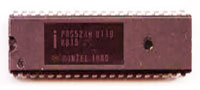
This is a page about my freeware 8051 / 8052 IDE program which is an editor / emulator / debugger / assembler / disassembler / ISP programmer for the 8052 all in one portable Windows executable. Many years ago when I was programming the 8052 professionally and at home, tools were very expensive. There was not much freeware or opensource, but trough my employer I had most of the tools I needed. I wrote a lot of programs in 8052 assembler in 8052 assembler and PL/M, but I also learned to write in C and I had a good C compiler for the 8052. The 8052 was a genius design for its time and its funny that this processor is still used a lot. For development and debugging 8052 assembler code, this freeware IDE can be used. Regards, Hein Pragt.
I also have a Facebook Group on Retro Computing and Electronics, feel free to join!
8052 editor / assembler / emulator / debugger

To be able to program for the 8052 you need an assembler or compiler. I personally still like to write in 8052 assembler but I could no longer find tools for Windows 10. There were still some programs to download but most of them worked at DOS level, had serious bugs or did not fit my needs. After some searching I decided that it was time for a new project, building a complete integrated 8052 development environment. I found a pretty good assembler and the base code of my Z80 IDE and I had some olde code in my code library. The result is 8052 workbench, a portable x64 Windows program that includes an editor, assembler, disassembler, emulator, single step debugger, Intel hex read / write function a VT100 terminal window, a seven segment display with 8 LEDs and keyboard support.
Installation
Download the zip file and unzip it at the place where you want to install it on your hard drive. Then create a shortcut to the program to the desktop and the program is ready for use. It is a so-called portable program which means that it does not use external sources or libraries and does not use the registry. After removing the directory from this program, it has also disappeared completely from your system.
First time use
To practice there is an example4.asm file in the example directory, which you can load after which it will be in the shown in the middle edit window. Now you can convert this into machine code by means of the assemble button, this will appear on the left of the screen and be put into the virtual memory of the emulator. The last (or first) .org statement will also be put in the program counter and by simply pressing the run button you can execute the program and follow it on the screen. This will not be very fast because every instruction will perform a screen update of all registers. If you want the program to run faster, you can disable the update of the registry block by means of the update checkbox. You can now modify the program, reassemble it and run it again.
In de example directory there are also two 8052 Basic versions from Intel that will run fine in this IDE emulator. After the assembler and RUN hit the spacebar (just as in the original autobaud detect) and the prompt will be shown.
There are more example files, a lot of them I made myself when testing the IDE and some I found on the Internet and are free to use.
By means of the step button you can execute the program instruction by instruction and check the output and the registers. You can also enter the break address, the emulator will then stop at a run command at this address and display the registers of that moment. When 0000 is entered in the break field it will be ignored.
You can save the modified code as an asm file again but also save it as a hex file so that you can load the binary code in a circuit or ep(rom) for a real 8052 circuit. You can also read an Intel-Hex file, which will then be loaded into the internal emulator memory. You can also run tis code when you put the correct start address in the program counter. You can also disassemble this internal emulator memory code after which the source code will appears in the edit screen in the middle. This can then be changed and written back into the emulator memory by means of assemble button.
I/O map
The 8052 has no I/O space so the LEDS and seven segment display are mapped on port 1 and 2. You can put the leds on port 1 or 2 and the display on lines port 1 or 2 and character port 1 of 2. You can select this with the top menu, or with some extra assembler directives I added. Look in the example files to see how they work.
- The keyboard is send to the serial buffer of the 8052 (SBUF) and the display is also connected to the serial (SBUF) of the 8052. I also pulse the character on the RX pin to enable autobaud detect and simulate the hardware as good as possible.
- Interrupt lines are connected to the interrupt buttons at the top of the screen, when pushed they will activate the interrupt lines.
- The output ports are shown at the top as input values and output values, they can be modified to test input / output code.
LED I/O modes
In led I/O mode 1 the leds are connected to port 1 and a 1 on the port makes the led light up, directive is ;#LED1

In led I/O mode 2 the leds are connected to port 2 and a 1 on the port makes the led light up, directive is ;#LED2
Seven segment display modes
In Seven segment mode 1 the leds are connected to port 1 is select of segment and port 2 is display data. The data is latched so the displays keep their value even if they are no longer selected. Directive is ;#SEVEN12

In Seven segment mode 2 the leds are connected to port 2 is select of segment and port 1 is display data. The data is latched so the displays keep their value even if they are no longer selected. Directive is ;#SEVEN21
Interrupt pins configuration
The I0, I1 and I2 buttons ar the top of the screen are connected to the interrupt lines to simulate external interrupts.

User define buttons configuration
There are also four user define buttons on the seven segment panel, these are connected to P1.2 to P1,5 to simulate external switches.

Supported processors
The current version supports the Intel 8031, 8032, 8051, 8052 and Atmel 8952 processor. For the Atmel 8952 processor this IDE had a ISP In Circuit Programming mode, that supports a serial Arduino ISP module to update an 8952 processor from within the IDE. You can edit code, run and debug it on the emulator and then test it on a real 8952 processor. The hardware configuration of the IDE is equal to a cheap 8952 development board from China.
Supported development board
I use this development board, you can order it in my webshop, its very complete, you have to solder it yourself. It had a Zif socket for the processor, a full rs232 circuit, and USB circuit, four pushbuttons and a reset button, am ISP programming connector, eight output leds, a power supply, crystal in socket and all I/O lines on connector pins.

Link: https://www.heinpragt.nl/?product=avr-development-board-kit
Schema of this development board

8952 ISP programmer using Arduin nano
I created my own Arduino Nano based ISP programmer for the 89S52 processor. I connected it to the Chinese development board with a standard ISP connector cable and I guess this will work on other 8052 ISP development boards as well. I chose this development board because it is very cheap and has a lot of features. And of course an Arduino Nano is small and also cheap.

Schema of Arduino Nano ISP programmer

Download Arduino Nano sketch for the ISP programmer.
*) This will also work with an Arduino Uno board!
Version 1.04
I use the 8052_workbench myself and that is one of the way I find and fix bugs. One of the last things I did was recode de TB31.asm file, a complete Tiny Basic interpreter for the Intel 8031 and made it work fine on 8031 with 128 bytes internal ram. During this process I found some little bugs in de emulator and I added a mode to emulate a real 8031 (128 bytes memory checks) to the code. Also I fixed code that would destroy the user interface if there was too much output to the windows. And the most important new feature is the ISP In Circuit Programming option. The example directory now also contains the Intel 8052 floating point basic assembly sourcecode, the complete 8031 tiny basic assembly sourcecode and the paulmon21 assembly sourcecode. I proudly present version 1.04 of the 8052 developer IDE.
Download
Here you can download the latest version if this IDE. This download is a zip file containing a portable x64 (and a x32 version) Windows exe programs, an assembler directory and a examples directory. After weeks of debugging I think the project is ready for release, if you find any bugs please report them to me.
https://www.heinpragt.nl/?product=8052-processor-ide
- Version 1.04
- Added full timer 2 support.
- Added ISP upload feature
- Change Led polarity to match development board.
- Added four buttons to LCD panel.
- Fixed P3 display in register panel.
- Fixed windows corrupt on to much update.
- Fixed SETB to handle LEDS correct.
- Version 1.03
- Fixed error in IDE update windows that would destroy the IDE context menus.
- Fixed ADDC flags error.
- Fixed MOVC A,@A + PC instruction.
- Fixed DA A instruction AC flag error.
- Fixed SUBB OV flag error.
- Added 8031 emulation checkbox.
- Version 1.02
- Fixed a last minute change error in the terminal code that made keyboard not respond.
- Fixed the name of the example directory.
- Fixed a unwanted quote character in exampkle4.asm.
- Version 1.01
- Initial release, it might be not completely bug free, I will test on, wait for remarks amd release the next version soon.
8052 links, tips and documents
- Intel 8051 wikipeadia A wikipeadia page about the Intel 8051 processor.
- 8051/8052 – MEVIHUB A webpage with a lot of infromation on the 8052 processor.
- 8052.com A website dedicated exclusively to the 8052 microcontroller.
More pages on software development
[catlist name=”Software development”]
MC14500B processor IDE

This is a page about my MC14500B IDE program which is an editor / emulator / debugger / assembler / disassembler / ISP programmer for the MC14500B, all in one portable Windows executable. I learned about the MC14500B one bit processor on an Internet forum and I was facinated by this little device. I ordered a PLC14500 board from Tindie and designed mt own hardware, a breadboard design and an Arduino shield version. There ere no real tools but the processor is quite simple and reading the datasheet and the programming manual I wrote an assembler and disassembler and an emulator, then I decided to adap my IDE framework for the MC14500B processor. It took som time to create a fully working hardware emulator for the PLC14500 board and a working emulator for my own board, and I tried to visualize the boards on screen. Then I write my own bootloader for the Arduino Nano and added the ISP option to the IDE so you could upload the code directly to the boards. For development and debugging MC14500B assembler code, this IDE can be used.
Regards, Hein Pragt.
I also have a Facebook Group on Retro Computing and Electronics, feel free to join!
MC14500B editor / assembler / emulator / debugger

To be able to program for the MC14500Byou need an assembler or compiler. I like to write (puzzle) in MC14500B assembler but there were no real usefull tools available for for Windows 7,8,10,11. After some searching I decided that it was time for a new project, building a complete integrated MC14500B development environment. I wrote an two pass assembler and used the base code (framework) of my Z80 and 8052 IDE. The result is MC14500B workbench, a portable x64 (and X32) Windows program that includes an editor, assembler, disassembler, emulator, single step debugger, Intel hex write function, a VT100 terminal window and a ISP programmer.
Installation
Download the zip file and unzip it at the place where you want to install it on your hard drive. Then create a shortcut to the program to the desktop and the program is ready for use. It is a so-called portable program which means that it does not use external sources or libraries and does not use the registry. After removing the directory from this program, it has also disappeared completely from your system.
First time use
To practice there is an example directory, from which you can load example programs after which it will be displayed in the editor window. Now you can convert this into machine code by means of the assemble button, this will appear on the left of the screen and be put into the virtual memory of the emulator. By simply pressing the run button you can execute the program on the selected on screen board and follow it on the screen. This will not be very fast because every instruction will perform a screen update of all registers, ports and leds. If you want the program to run faster, you can disable the update of the registry block by means of the update checkbox. You can now modify the program, reassemble it and run it again.
Ifyou have a board connected you can use (select) the terminal window to “talk”to the Arduino Nano, and if you have loaded my bootloader, you can then simply upload the code to the board using the ISP menu. This is also the menu where you select the communication port.
In the main directory there is also the .ino sourcecode file of my custom bootloader for the Arduino Nano. Just load the code in the Arduino IDE, compile it an upload it to the Arduino Nano using the serial cable. You can now check the code inside the Arduino eeprom or do a factory reset (smoketest program) on the board using the Arduino IDE terminal of the terminal of my IDE at 9600 Baud,
By means of the step button you can execute the program instruction by instruction and check the output and the registers and ports. You can also enter the break address, the emulator will then stop at a run command at this address and display the registers of that moment. When 0000 is entered in the break field it will be ignored.
You can save the modified code as an asm file again but also save it as a hex file so that you can load the binary code in a circuit or ep(rom) for a real MC14500B circuit. You can also disassemble the internal emulator memory code after which the source code will appears in the edit screen in the middle. The assembler and disassembler are default loaded with all the friendly names of all the I/O in a standard symbols table. This generated sourcecode can then be changed and written back into the emulator memory by means of assemble button.
I/O map
The IDE currently supports two hardware boards that will be displayed on the screen with working leds and buttons. Inside the IDE is a real hardware emulation of the complet circuit of the board and all the chips so it should work exactly as the real hardware. My board is not yet ready but I am using this tool to debug it. My board will support JMP and RTN instruction with a ONE level stack :-). With the top menu you call also connect te VT100 terminal to the input and output lines of the board, this will be useful on my board.
Version 1.02
Version 1.02 is the second version with some improvements after testing with different hardware. I will be maintaining the program based on my own needs, bug reports and feature reuests.
Download
Here you can download the latest version if this IDE for a small fee. This download is a zip file containing a portable x64 (and a x32 version) Windows exe programs, an examples directory and my custom Arduino Nano boatloader sourcecode. After weeks of debugging I think the project is ready for release, if you find any bugs please report them to me. The progams are digitally signed using my codeding certificate for your safety and to make them thrusted by Windows. It seems my IDE programs work fine on (Linux) WINE as well.
Download at: https://www.heinpragt.nl/?product=mc14500b-processor-ide
- Version 1.02
- Fixed error in hex dump bootloader (16e byte);
- Improved ISP uploader for PLC14500 board;
- Improved ISP uploader for HP14500 (Arduino shield) board;
- Fixed terminal bug in HP145000 emulation.
- Version 1.01
- Initial release, it might be not completely bug free, I will test on, wait for remarks amd release the next version soon.
MC14500B links, tips and documents
- My technical page aboput the MC14500B processor;
- Retro trainer board based on the MC14500 1-bit ICU. The project is OSHW certified and is available on Tindie;
- Wikipedia page about the MC14500Bprocessor;
- A hackaday.com MC14500B microcontroller project;
- A MC14500B programmers handbook (pdf).
More pages on software development
[catlist name=”Software development”]
Http health check monitor

 As a technical application manager I face the problem of having a complex application with many servers and lots of api services, and sometimes one or more of the many http servers or rest api’s fails. There is excellent tooling to monitor an application farm but a lot of companies do not invest in this kind of health check maintenance tooling especially not in de development area. Giving the fact that a lot of technical maintenance is done by the devops team and they also don’t have the health check tooling to monitor the servers. I am a programmer so decided to build a small portable dotnet program that could generate a real time status view of all the http(s) services in an application suite. It is a simple http server that will run on any chosen port (default 8080) and it reads a simple xml file with a list of url’s it has to poll and what result status code is expected. When the expected status code is returned it will show a green bar and when the status is different it will show a red bar with the server name and the http error code. The program is a simple x64 DotNet 4.6 console application that you can run from the command line, or at server startup, from a scheduled task.
It expects a settings.xml file and a style.css file in the same directory, the xml file contains a list of all the url’s the program has to poll. It looks like this:
<servers>
  <server>
    <group>Dev</group>
    <name>Server one VM00345:8080</name>
    <url>http://www.system1.com:8080/health</url>
    <valid>200</valid>
  </server>
  <server>
    <group>Test</group>
    <name>Server one VM00347:8081</name>
    <url>http://www.sever11.com:8081/api</url>
    <valid>401</valid>
  </server>
  <server>
    <group>Test</group>
    <name>Server two VM00385:80</name>
    <url>http://www.apigate.com/test</url>
    <valid>200</valid>
  </server>
</servers>
To give users a chance to change the layout or colors of the healt monitor screen, an external css file is provided, it will be read at startup. It only contains the basics, but if you f.i. use short names you could change the width of the blocks (entry) so more blocks can be displayed on a singe screen. It looks like this:
.ok { background-color: lightgreen; }
.error { background-color: red; }
.entry { width: 320px; padding-left: 8px; padding-right: 8px; margin-left: 4px; border: 1px solid gray; float: left; }
.header { font-size: 1.5 em; padding-bottom: 4px; margin-bottom: 4px; }
.timestamp { font-size: 0.6em; }
.groupend { clear: both; }
.groupbar { width: 99%; color: #ffffff; background-color: gray; margin-top: 6px; }
Since version 1.09 there is a config.xml file where some configuration settings are stored in simple name value format. The commandline port will still overide the config.xml setting.
 <settings>
   <setting> <name>Port</name> <value>8080</value> </setting>
   <setting> <name>TimeoutMs</name> <value>2200</value> </setting>
   <setting> <name>Title</name> <value>Development</value> </setting>
</settings>
Every time you send a GET request to this health check monitor program the internal http server will poll all he url’s and generate the html status screen. It will not poll until the next GET request, the date time stamp of the last request is in the top of the screen. This http health check program is KISS (keep it simple stupid) and does what it has to do and nothing more. Its portable and does not need installation and it runs anywhere you put it. It only needs the dotnet 3.1 (or higher) installed. The program is closed source, freeware and without any warranty whatsoever. But I use it myself and I think it’s simple, stable and safe. Any recommendations for improvement are welcome.
Download the zip file of the https health monitor program and unpack it in a (logical) folder on your disk drive, I use a folder named portapps in the root folder of my C drive. Run the http health check monitor program by hand (the argument can be a different port number), double click it for the default port and it will start a console application. As long as this console applicatio is running the http server is alive. In the console window it will log all the things it does, including more details on the response codes. Start you browser and type: http//localhost:8080 and the status screen will be displayed in you browser. The timeout on every request is 1.5 seconds, so if a lot of servers are down, the response screen will take a while to load. If you open the port number in the firewall, the http server can also be used on another (client) computer.
Versions
Version 1.09 – Feb 2021 – new features.
Here you can download the zip file with the lates version 1.09 of the HmPHealtheMonitor.exe portable Windows ™ health check monitor program. The executable file is digital signed with my heinpragt.com codesigning certificate. Read the intructions to use above.
Download: HmPHealthMonitor109.zip
Release notes
- 1.03
- Initial release
- 1.04
- Add timeout of 1.5 sec.
- Now listening on any IP
- 1.05
- Added support for old and invalid TSL/SSL versions.
- 1.06
- Added explicit GET methode.
- Improved error handling.
- 1.07
- Improved TSL/SSL handling.
- 1.08
- Fixed bug in 404 errorhandling.
- 1.09
- Added configurable timeout value for each call.
- Added a configurable title for the header.
- Added a config.xml file.
Known issues
- The windows defender program will sometimes block this program, just right click the exe file and click run anyway.
- The Avast virusscanner sometimes gives an alarm, I double ckhecked, it is a false positive.
How to install the Health monitor as a service in Windows ™
When you want this health check monitor to run at a Windows server at startup, one way is installing it as a server and set the startup mode to automatic. This also gives the opportunity to run it under another account. There is a nice open source wrapper that can run ANY windows executable (but also runnable jar (Java) programs) under windows as a service. You can find the binary distribution (but also the source code if you need it) at Github, it is the WINSW project for dotnet version 4 with the name: WinSW.NET4.exe, Jus Google it and download it from Github. This is a short manual for this purpose, you can also use it for other programs.
- Copy the file to the directory containing the executable.
- Rename the file WinSW.NET4.exe to HmpHealthSrc.exe.
- Create a xml file with the (same) name HmpHealthSrc.xml.
- Edit this file and change the content to this:
<service>
  <!-- ID of the service. It should be unique across the Windows system-->
  <id>HmpHealth</id>
  <!-- Display name of the service -->
  <name>HmpHealth WinSW</name>
  <!-- Service description -->
  <description>HmpHealth on port 8080</description>
  <!-- Path to the executable, which should be started -->
  <executable>E:\HealthMonitor\HmPHealthMonitor.exe</executable>
  <arguments> </arguments>
</service>
- To change the port, just put it in arguments.
- Open a CMD shell and go to the HealtMonitor directory.
- Type: HmpHealthSrc install to install the service.
- Open the service manager and check i fit is set to autimatic and start the service.
- Check, using the browser if the Health Monitor is running.
WINSW commands:
- ‘install’ – install the service to Windows Service Controller
- ‘uninstall’ – uninstall the service
- ‘start’ – start the service (must be installed before)
- ‘stop’ – stop the service
- ‘restart’ – restart the service
- ‘restart!’ – self-restart (can be called from child processes)
- ‘status’ – check the current status of the service
- ‘test’ – check if the service can be started and then stopped
- ‘testwait’ – starts the service and waits until a key is pressed then stops the service
- ‘version’ – print the version info
- ‘help’ – print the help info (aliases: -h,–help,-?,/?)
More pages on application software
[catlist name=”Application software”]
CpmBox a CPM 2.2 emulator

The second operating system I used (after TrsDos) was CPM on a Z80 development machine. Some time ago I build the Z80 MBC2 board and I played with CPM again. I included a fully working MBC2 emulation in my Z80 IDE program but after using DosBox I got the idea of creating CpmBox. CpmBox is a full CPM 2.2 implementation on a Z80 emulator for Windows, including a VT100 terminal and 8 CPM disks based on the MBC2 with the looks of a real terminal. It is a portable windows program (one single executable) and the zip file contains the emulator, a directory with a lot of disks and the bootdisk and a dos based directory to load CPM files from and to dos. It is also possible to save and load programs from dos and save or load them to a CPM disk. It is freeware and I hope you like it. . Regards, Hein Pragt.
Copyright
I respect copyright and I will not distribute illegal software. Part of this program was inspired by the Z80 MBC2 project and the boot disk and bootloader are from this project. I kept them as they are. The CPM disks are filed with old CPM based software I had in my collection and I filled the first 6 disks with all kind of software. Legally some of this software maybe is still copyrighted BUT in my opinion the copyright was from 40 to 45 years ago, these products have not been on the market for a lot of years and I think that most company’s will not complain. I do not ask any money for this package and the main goal is to keep the old spirit alive. I anyone can identify him or herself as a legal copyright owner and has problems with the distribution I will remove that content. But I seriously believe there is no one to object to distributing these old artifacts as freeware. My program itself is closed source but freeware.
What is inside this emulator
This emulator is exactly like a Z80 MBC2 computer running CPM 2.2 (without the i/o chip) and connected to a VT100 terminal.
- Emulates: Z80 and VT100 terminal;
- OS: CPM 2.2;
- Keyboard: full 53 keys emulated by the PC keyboard;
- CPU: Zilog Z80 the speed is depending on the PC hardware;
- RAM: 64 kb;
- Textmode: 24 x 80 characters;
- Graphics: None;
- Color: White on green screen;
- Sound: None;
- I/O: 15 CMM disks and access to DOS disk;
- Design: Like an old terminal screen.
Download
Here you can download the latest version if this CpmBox emulator. This download is a zip file containing a portable x64 (and a x32 version) Windows exe programs, a directory with CMP disk images and a directory for DOS based CPM files. It is a portable program, just unpack it somewhere on the disk and start it by clicking it. This program is digitally signed with my own code certificate and it is trusted by Microsoft windows.
Download x64 (and x32) version 1.01 of CpmBox (2022)
- Version 1.01
- First (beta release) version, the program has been testen by myself on my hardware.
CPM disks
I made some disks for this program and I got a question about how to make and maintain the disk image files. I have searched for a solution myself for a while until I found a utility program called cpmtools. But it were command line tools and not so user friendly. Then I found a gui for this toolkit and although the visual views are sometimes a little strange because of misinterpreted characters, it works fine. I zipped the complete directory as it is on my disk, including the correct disk definitions. You can download it here. Just download it and unpack it somewhere at your harddisk. Just doubleclick: CpmtoolsGUI.exe.

First you select a disk image in the upper left corner (or create a new one) and then you select the disk format. I use the disk formats of the MBC board project, use d0 for bootdisk 0 and d1 for alle other disks. You can now select the directory on you own harddisk in the right corner and you can select a file in the cpm view of the dos view and use the buttons to mover them from dos to cpm, or from cpm tp dos. I can read other cpm disk formats as well. This way you can create your own cpm file repository on your hardisk and copy them to the cpm disk images. This tools is not that user friendly and not very beautiful in UX but ir works fine for me.
More pages on emulator software
[catlist name=”Emulators”]
Minimal Emulator Frontend

There are a number of great emulator frontends available on the Internet, I use retropie on a mini Nes with a Raspberry pi. But for my Windows 10 desktop there are only programs that are huge, with a lot of artwork and sounds, not user friendly and sometimes very hard to configure. After some disappointing experiences I decided that I needed a very simple frontend, just select a game and double click it and it will run on the correct emulator. As always when I cannot find what I need I write it myself, I am an experienced C and C++ programmer and I know how to write portable Microsoft Windows programs. I still have a backup file with a lot of game roms, I only needed to find some stable and portable emulator programs for these game machines. And these game emulators had to have a command line interface to start the emulator with a predefined game rom.
I tested some emulators and after a while I had a good collection of free, portable emulators that I could deliver together with my frontend program. The reason I also package these emulators is that I can predefine them in my machines config file so that the program needs no configuration and will work out of the box. I cannot package any game roms as they are copyrighted, you have to find the game roms yourself. But just copy them into the roms directory in the subdirectory of the game system and the next time the program starts it will scan and add this game to the list. The program is very simple but does exactly what its needs to do and has a user friendly interface. It will work out of the box, there is no need for configuration. There are two config files that are just plain text and you an edit them to add friendly names to the games of to add of delete a game emulator.
To install it just download the zip file, it will contain the exe file and some predefined directories. In the emulators directories there are several preinstalled portable emulators, you can update them yourself as they are free available on the Internet. When you start the program you will have an empty screen, that good. Now just copy the rom files from your archive to the roms directory in the correct folder of the game system and after that start hpmef.exe again and the games should show in the list. Just DoubleClick on the game and the correct emulator should be started with the correct game rom. There are two config files, the file games.txt is a generated file you can edit only the third column and that is the friendly name of the rom and also the display name. By default this is a copy of the rom filename. This friendly name will not be overwritten and will last as long as the file is not deleted. You can delete the file and start the program again, this will generate a new games.txt file.
The second configuration file is the machines.txt file that contains all the game emulators and the abbreviation used to connect the game emulator to the game. It also contains the file mask of the roms for this system. You can edit this file and delete or add emulator programs. Always add new emulator programs under de directory emulators and then add the manually to the machines.txt file. This is the only real configuration you need to do, only if you want to change the default setting. This file will not be created new, so do not delete it and make a backup copy. This program is digitally signed by me so it should be trusted by Microsoft Windows ™. The program is freeware, you may copy it as you like, use it as you like, but there is no warranty whatever. I am a good programmer and I do not expect this program to do anything bad tot your system, but I cannot be responsible for the way people use it so there is no warranty from my side for the use of this program. But my site is trustworthy and I consider myself a trustworthy programmer, but I have to mention this warning.
Download the zip file and unpack it in a (logical) folder on your disk drive, I use a folder named portapps in the root folder of my C drive. It will create a directory structure and add some files. Just make a shortcut to the hpmef.exe file or DoubleClick it to start the program. If you find a bug or have any good suggestion to improve this program you can contact me trough the contact form on this site.
Versions
- Version 1.01 – Aug 2020 – initial release.
Download
Here you can download the zip file with the lates version 1.01 of the hpmef.exe (Hein Pragt Minimal Emulator Frontend) portable Windows ™ program. This version supports a Gameboy emulator, Gameboy Advance emulator, Nes emulator, Super Nintendo emulator, Nintendo 64 emulator, MSX emulator and Sega geam gear emulator. Have fun!
Download: hpmef101.zip
Links to the emulators homepages
- Homepage of the BGB GameBoy emulator.
- Homepage of the bsnes Super Nintendo emulator.
- Homepage of the FCEUX Nintendo Entertainment System (NES) emulator.
- Homepage of the MSX emulator.
- Homepage of the KEGA Fusion SEGA emulator.
- Homepage of the Project64 Nintendo 64 Emulator.
- Homepage of the VGBA emulator.
More pages on application software
[catlist name=”Application software”]
hmpFileFind utility

As a Windows software developer for many years I had a directory with all small portable utility programs that I put on every system that I had to work on. HmpFileFind is a simple portable freeware application that helps find files on a filesystem (recursivly) by file pattern and file content. A lot of time I wonder where on my 3 Terabyte hard disk did I put this file and then I use this little application to locate it. I can search the disk for a (wildcard) filename, but also on a word or phrase in the file. As a web developer I sometimes wonder where have I used this link or this word or phrase on my website, then I select the root file of the website on my hard disk, select to only look into *.html files and type a word or phrase that I want to look for. The listbox will be filled with all the filename and the file paths of the files and just double click on the filename to open it in the preferred editor. Regards, Hein Pragt.

What kind of application is HmpFileFind
This program is very simple, it does not maintain a database it does not keep any internal information and is privacy friendly to use. The only thing is that it saves the last settings and will reload the at the next time to save time. It will not make any modifications to the filesystem and it will only search for a word in a file if the search field is not empty. It can find words in all files that contain text not in binary files.
The program is small and limited, you cannot use regular expression in the search phrase and when searching through a lot of files, this will take some time. The program is portable and is not depending on any other library or runtime, it comes in a X32 and X64 version and the exe files are digitally signed by a coding certificate for your safety. Just unzip the file somewhere on your disk and click to program to start it. A very handy utility for finding your files (that contain certain words) on big filesystems.
Download
This program is digitally signed with my own code certificate and it is trusted by Microsoft windows.
- Version 1.01
- Initial release, it might be not completely bug free, I use it a lot myself, I will wait for remarks amd release the next version soon.
More pages on application software
[catlist name=”Application software”]
PragtFotoManager utility

Twenty years ago I bought my first digital camera and there were almost no programs to manipulate digital photo’s. So I wrote a little program to fit my needs and for a few years I even sold it. After a few years I decided to make it freeware and this is the last version I compiled. (Currently I cannot compile it anymore, so this is the final version). The program is in the Dutch language and there is no English version. PragtFotoManager is a small portable program that allows you to perform one or more operations on one or more (up to a maximum of 999) photos. The operations are: rename photos, resize photos, create thumbnails, save information from photo, create photo index pages and provide photos with a copyright text. (Watermark). You can perform these operations individually but also run them all at the same time. The program is especially useful when you need to edit large amounts of photos, for example for a website or sending by email. The program will not overwrite your original photos (except when renaming) but creates a copy of the photo with the desired operation. It is not a very modern program, but it still can be very useful. Regards, {-Hein Pragt}.
What kind of operations can it do?
1. Rename photos
Often you have many photos on your hard drive and the file names are not always clear. Most cameras number the photos with a fixed prefix. You can manually rename the photos, but that is often a time-consuming job. This program makes it is possible to select several photos and to provide them all with a meaningful name and serial number in one operation. You can enter the numbering prefix, start number, and interval. You can also adjust the order of the photos before renaming so that after renaming they form a logical whole. For example, when you edit your holiday photos, you can include the place and date in the name.
2. Resize photos
As the number of megapixels of cameras is constantly increasing, the photo files are also getting larger. When you want to send these photos by email or put them on a website, the files are often too large to send and much too large to display on a normal web page. If you put the photos on your web server in a large size but display them in a reduced size, you will consume a lot of bandwidth and your pages will load slowly. Resizing and optimizing photos will make your pages load faster. With the help of this program you can quickly and easily resize photos. You can reduce the photos to a number of standard sizes (800×600) (640×480) (320×240) or enter your own size. The photos will be re-sampled so that the resized photo remains of good quality. To prevent overwriting, the reduced copies will be placed in a subfolder named by the width and height of the format by default. So you can see at a glance what size the photos are in these subfolders.
3. Put copyright text on all photos
You can also automatically place a small (copyright) line of text on every photo when you are resizing, with a selected foreground and background color. This option is useful, for example, to include a copyright notice (watermark) in the photo. The position of this copyright text can be adjusted and you can also place this text in the border around the photo. This option is very useful when you use the want to publish photos on the Internet and clearly state your copyright.
4. Generate thumbnails
Thumbnails are extremely reduced images that can be included in a link on an internet site, for example. You can determine the maximum height and width yourself. The thumbnails will be written in a subfolder thumbs by default, you can adjust this setting yourself. When resizing, the width to height ratio of the original photo will be used. When you post photos on the Internet it is recommended to use thumbnails on the overview page and not the reduced size versions of the photo to make the page load faster and save bandwidth.
5. Convert to another file format
If you want to convert your photos to a different storage format, you can of course do this with a graphics program (such as Photoshop). When you have a large number of files to convert, it may take some time as you will need to open and re-open each file. Pragtfotomanager allows you to convert a large number of files to another file format at once. The input formats can be mixed JPG, GIF or PNG, the output formats are JPG, GIF and PNG.
6. Store EXIF data
Modern cameras save the settings of the photo as extra data (exif). You can make this exif data visible by loading the photo into Photoshop, for example. However, after editing in some programs this information is lost. Since it is important for a photographer to have this exif data such as aperture and shutter speed setting available in text form Pragtfotomanager saves this data in a text file. Pragtfotomanager can create a separate text file for each selected photo with the same name as the photo (extension TXT) where this information will be writtem in readable form. You can also choose to write all this information into one file.
7. Make index sheets
Some photo print centers provide an index sheet. It contains the thumbnails of all photos and the name of the photo. This is very useful when reordering. These index sheets are also very useful to manage your collection of photos. This program can automatically generate index sheets from the selected photos. You can determine the size of the index pages and the size of the thumbnails. The program itself will format it and calculate the number of thumbs per page.
All these operations can be performed separately, but also all at the same time. The program will save the last settings when exiting so that you do not have to re-enter all the settings every time.

Download
This program is digitally signed with my own code certificate and it is trusted by Microsoft windows.
More pages on application software
[catlist name=”Application software”]
PragtTextUtil utility

As a Windows software developer for many years I had a directory with all small utility programs including many Unix utilities that I put on every system that I had to work on. This worked fine for many years until I switched to Windows 7 and all these command line tools stopped working. I had to make a choice to recompile all these programs for Windows 7 or collect all the features of these small utility programs and merge them into one portable Windows application. I chose the development of the portable Windows application PragtTextUtil (PTU) that I hereby offer as a freeware application, for everyone that does development or maintenance on Windows based computers. Regards, {-Hein Pragt}.
What kind of application is PragtTextUtil
 PragtTextUtil is not an text editor although the basic functions to edit text are present in the program. The program aims to perform operations on text such as converting to upper or lowercase letters or removing HTML tags and converting them to neat paragraphs. But also operations as trim, uniq, sort and filtering are present in this application and also a complex operation to generate a sorted word frequency overview to be able to determine, for example, good keywords for a web page. For example, you can filter from a log file all lines that contain a certain word or not a contain a certain word. Also a nice option is search and replace with the ability to use CTRL characters in the search but also the replace text.
As input, the program of course can read all forms of plain text files, but also files as hex/ascii dump, html pages, web pages via an HTTP request (simple wget) to get the exact response of an internet server. But you can also load the contents of your directory into the text editor to for example, create a sorted list of all your music. (Under Windows, it’s still not possible to cut and paste the list from the explorer). You can also use the output of a command line read command directly into the text editor. With the function to request a web page you can load the HTML of this page into the text editor after which you can easily remove all HTML tags and scripting and then convert the bare text to neat paragraphs that you can further edit in your favorite word processor. This allows you, for example, to also retrieve texts from sites that try to block the cutting and copying of the text.
Menu options overview
| File New Open as text Open as Unicode text Open as text (read first 50 lines) Open as text (read last 50 lines) Open and convert to hex/ascii Open from HTTP Open and pipe command line Save text Save text As Read directory listing (date/size/name) Read directory listing (names) Search trough files Compare files Exit Edit Undo Select All Copy to clipboard Cut to clipboard Paste from clipboard Delete selection Search text Replace text Goto line | Operations ToUpper selection ToLower selection Smart ToLower to paragraphs Whitespace to single space Whitespace to single space (save linebreaks) ToWordList (whitespace to inebreaks) Count lines, words, characters Words statistics (whole document) Sort Sort selection Asc Sort selection Desc Sort selection Asc (Ignore case) Sort selection Desc (Ignore case) Filter Strip html (add linebreaks) Format html Trim leading and trailing spaces Uniq the selection Uniq the selection with count Filter the selection (delete all except) Remove in the selection (delete all that contain) UTF-8 to iso-8859-1 UTF-8 to plain ascii (remove diacrites) \n (Unix) to \n\r (Dos/Windows) Help About |
Download
This program is digitally signed with my own code certificate and it is trusted by Microsoft windows.
Previous releases
Download. (Version 1.04 Jul 2011)
Download. (Version 1.03 Jul 2011)
Download. (Version 1.02 Jun 2011)
More pages on application software
[catlist name=”Application software”]
INS8060 or scmp processor

This page is dedicated to my fist microprocessor, the INS8060, also called the SC/MP processor. At the time I was 13 years old and did not have much money, I could afford to buy an electronics magazine called Elektuur every month, and they published a simple computer board based on the SC/MP processor. I was very interested in computer technology at that time and I read all I could about the SC/MP processor. As I did not have the money to buy a board I would draw the internal of the processor on a big piece of paper, with the RAM / ROM / keyboard and display as registers and I would have a lot of small zero and one papers to simulate the flow of the bits and bytes in the (paper) circuit. Looking back this was ridiculous, but this is the way I learned computer design and binary logic. By the time I learned the Z80 system I had good knowledge of processors and binary logic. I also saw a board called the MK14 that was based on the SC/MP as well, I considered buying one at the time, but I decides to go for a real computer. Still the SC/MP is my first processor and nowadays you cannot get the processor anymore (at least not at a reasonable price), but there are emulators in software and hardware that are still available. I have to say that I recemtly bought a SC/MP processor in China for 20 Euros. On this page I will share all documentations, links, schematics and code that I have or have found. Regards, Hein Pragt.
I also have a Facebook Group on Retro Computing and Electronics, feel free to join!
About the INS8060 or SC/MP Processor
National Semiconductor introduced the INS8060 or SC/MP In April 1976 and it was intended for small and cheap industrial controllers. The acronym SC/MP stands for Small Cost-effective Micro Processor and it needed few external components and was simple to program. In 1977 Elektor Magazine devoted a few issues to the SC/MP and the Elektor design came in two versions, a simple basic one and a version with a hexadecimal keyboard, 7-segment displays and a monitor program in ROM, cassette interface and the option to connect a VDU. The INS8060 or SC/MP has a rather simple architecture and can address a total of 65536 bytes memory. Because only 12 of these address lines are connected to pins the addressing space is 4 kb bute the high four bits of the address were multiplexed on the data bus during the NADS-signal. The 64k memory is divided in 16 x 4096-bytes pages. Only a limited number of memory reference instructions can cross a page boundary.
The first INS8060 or SC/MP chip was developed in P-MOS technology and needed a positive power supply of 5 Volts and a negative of 7 Volts. Later National Semiconductor introduced the SC/MP-II that was made in N-MOS technology and only needed a single 5 Volt power. Three of the signals on the SC/MP-II were logically reversed (i.e. BREQ became NBREQ) so the SC/MP-II is not 100% pin-compatible with the first SC/MP-I. The INS8060 or SC/MP was not a powerful microprocessor but at the time it was cheap and simple to use. The SC/MP only an instruction set of 46 basic instructions and was rather easy to program at binary level. Beside the Elektor design there was also a one board computer implementation called the MK14, developed by Science of Cambridge Ltd, which was a company of Sir Clive Sinclair. These are still sold on Ebay sometimes but there are also great emulators in software and hardware. (PIC microcontroller).
INS8060 or SC/MP Pinout

The table below describes the various SC/MP signals and pinouts.
(A preceding “N” in the signal mnemonic signifies a negative active signal.)
| NRST | Reset Input | Set high for normal operation. When set low, aborts in-process operations. When returned high, internal control circuit zeroes all programmer-accessible registers; then, first instruction is fetched from memory location &H0001 |
| CONT | Continue Input | When set high, enables normal execution of program stored in external memory. When set low, SC/MP operation is suspended (after completion of current instruction) without loss of internal status |
| NBREQ * | Bus Request In/Output | Associated with SC/MP Internal allocation logic for system bus. Can be used as bus request output or bus busy input. Requires external load resistor to Vcc |
| NENIN * | Enable Input | Associated with SC/MP Internal location logic for system bus. When set low, SC/MP Is granted access to system busses. When set high, places system busses in high-impedance (TRI-STATE) mode. |
| NENOUT * | Enable Output | Associated with SC/MP Internal allocation logic for system bus. Set low when NENIN is low and SC/MP Is not using system busses (NBREQ-high. Set high at all other times.) |
| NADS | Address Strobe Output | Active-low strobe. While low, indicates that valid address and status output are present on system busses. |
| NRDS | Read Strobe Output | Active-low strobe. On trailing edge, data are input to SC/MP from 8-bit bi-directional data bus. High-impedance (TRI-STATE) output when input/output cycle is not in progress. |
| NWDS | Write Strobe Output | Active-low strobe. While low, indicates that valid output data are present on 8-bit bi-directional data bus. High-impedance (TRI-STATE) output when input/output cycle is not in progress. |
| NHOLD | Input/Output Cycle Extend Input | When set low prior to trailing edge of NRDS or NWDS strobe, stretches strobe to extend input/output cycle; that is, strobe is held low until NHOLD signal is returned high. (for slow memory) |
| SENSE A | Sense/Interrupt Request Input | Serves as interrupt request input when SC/MP Internal IE (Interrupt Enable) flag is set. When IE flag is reset, serves as user-designated sense condition input. Sense condition testing is effected by copying status register to accumulator. |
| SENSE B | Sense Input | User-designated sense-condition input. Sense-condition testing is effected by copying status register to accumulator. |
| SIN | Serial Input to E register | Under software control, data on this line are right-shifted into E register by execution of SIO instruction. |
| SOUT | Serial Output from E register | Under software control, data are right-shifted onto this line from E register by execution of SIO instruction. Each data bit remains latched until execution of next SIO instruction. |
| FLAGS 0,1,2 | Flags Outputs | User-designated general-purpose flag outputs of status register. Under program control, flags can be set and reset by copying accumulator to statusregister. |
| AD00-AD11 | Address bits 00 through 11 | Twelve (TRI-STATE) address output lines. SC/MP outputs 12 least significant address bits on this bus when NADS strobe is low. Address bits are then held valid until trailing edge of read (NRDS) or write (NWDS) strobes. After trailing edge of NRDS or NWDS strobe, bus is set to high (TRI-STATE) mode until next NADS strobe. |
| Databus | Output at NADS Time | During NADS time the four most significant bits of the addressbus are active at the outputs. Also some other special signals are available at the remaining database pinouts. |
| DB0 | Address Bit 12 | Fourth most significant bit of 16-bit address |
| DB1 | Address Bit 13 | Third most significant bit of 16-bit address |
| DB2 | Address Bit 14 | Second most significant bit of 16-bit address |
| DB3 | Address Bit 15 | Most significant bit of 16-bit address |
| DB4 | R-Flag | When high, data input cycle is starting; when low, data output cycle is starting |
| DB5 | I-Flag | When high, first byte of instruction is being fetched |
| DB6 | D-Flag | When high, indicates delay cycle is started; that is, second byte of DLY instructions being fetched |
| DB7 | H-Flag | When high, indicates that HALT instruction has been executed. (In some system configurations, the H-Flag output is latched and, in conjunction with the CONTinue input, provides a programmed halt). |
| Databus | Standard Output | |
| DB0-DB7 | Databus input/output | During the assertion of NWDS or NRDS data is written to or read from external devices. Except for NADS-time, at all other times the databus is floated in (TRI-STATE) modus. |
| Vcc | Plus 5 volts | Power lead |
| GND * | Ground (0 Volts) | Power ground lead SC/MP-II (P-MOS) |
| Vgg | Minus 7 Volts | Power negative lead SC/MP-I (N-MOS) |
| XIN/ XOUT | Clock Crystal inputs | A quarts crystal between these leads will determine the clock-frequency of the SC/MP CPU. The SC/MP-II has an internal divide stage so its clock-frequency divided by two. |
INS8060 or SC/MP Instruction format

The SC/MP executes either 1 or 2 byte instructions, the first byte is called the OPCODE the optional second byte is the OPERAND. When the most significant bit of the OPCODE is set to 1 it will be a 2 byte instruction, the programcounter (P0) is automatically incremented to fetch the OPERAND byte. Most 2 byte instructions are memory reference instruction that will access memory external to the CPU. With the exception of the ILD and the DLD instruction the SC/MP will initiate a single byte read or write memory access, the ILD and the DLD instruction will do a read-modify-write instruction.

The internal register set of the INS8060 or SC/MP is VERY simple, it has only a few internal registers.
Accu
This is a standard accumulator register that contains the result of the most operations and usually holds one of the source operands.
Extension
The extensionregister has a multi purpose usage, it can be used to hold secondary operands to the extension instructions, it can be also be used to temporarily save the accu and it can be used as an 8-bit index register to facilitate relative indirect addressing. Whenever the 2nd byte operand of a memory reference instruction (called the displacement) holds a value of &H80 the content of the extension register is taken as the displacement instead of the 2nd byte operand. Also the extension register is used for the build in serial I/O capability of the SC/MP. The MSB of the extension register is connected to the SIN input and the LSB is connected to the SOUT output line.
Status
The status register contains a number of standard flags like the carry flag and the overflow flag and the interupt enable flag. However, the carry and overflow flags are not directly tested by branch-instructions. They must be copied to the accu first (CAS-instruction) and their state must be ascertained with bitwise logical instructions. Branch testing is only done on the state of the accu-register. Flag F0, F1 & F2 are connected to the flag pins for output. Sense SA & SB that are connected to the sense input pins.
The Pointer Registers P0-P3
The Pointer registers P1-P3 are used as datapointer, stackpointer and subroutine / interupt service pointers. Pointer register P0 is used as the Programcounter, the main difference with a normal programcounter is the fact that the SC/MP PC is incremented prior to fetching a new instruction, so the program always continues the next instruction at PC+1. Another feature of all pointer registers is that whenever a pointer-register is incremented by a auto indexed addressing mode instruction or an effective address is calculated that crosses a page boundary, the effective address folds back to the beginning of the page. Only when loading an absolute address into the pointer register the page boundary can be crossed! National Semiconductor recommends the following pointer register roles as a rule of thumb: P0 = Program Counter, P1 = Data of I/O Pointer, P2 = Stackpointer, P3 = Subroutine/interrupt Pointer. The XPPC instruction can exchange the content of the PC with any of the other pointer-registers so any Px can service a subroutine but only P3 can service a service routine for an interupt, because the XPPC3 instruction is generated automatically whenever an interupt is received.
INS8060 or SC/MP addressing Modi
All memory reference instructions make use of addressing modes to calculate the effective address of the memory reference. This could be to access the content of a memory location but also to determine the target adress of a branch or jump instruction. The SC/MP features the following addressingmodes:
PC Relative/Pointer-register Indexed Addressing
The 2nd byte of an instruction is taken as a displacement in 2s complement fashion and added to the current content of the designated pointer register to calculate the effective address. When the PC (P0) is used as the designated pointer register we call this PC relative mode. A 2s complement 8 bit value can contain any value from 127 dec to +127 dec. In the case of a PC relative Jump (branch) one should take into consideration the the programcounter will be incremented by 1, prior to the next opcode fetch.
Indirect Addressing
In SC/MP documentation indirect addressing is regarded as a special case of PC-relative and indexed addressing, in the event that the second byte of an memory reference instruction contains &H80 as a displacement value it is not taken as a negative displacement of 128 dec, but the content of the extension register is used as the 2s complement displacement to calculate the effective address.
Immediate Addressing
The second value of the instruction in a memory reference instruction is immediately used as source data for the instruction, no further address calculation is required.
Auto Indexed Addressing
This addressing mode is a bit like Indexed addressing but this time the pointer register itself is modified by the displacement in a pre decrement and post increment way. In the case of a negative displacement the pointer register is replaced with the effective address and then the memory access is executed. In the case of a positive displacement the memory access is executed with the current value of the designated pointer register, prior to replacing Px with the new modified calculated EA value. In this way we can used P1, P2 or P3 as a LIFO stackpointer.
| Mnemonic | @-modes | Opcode1 | Opcode2 | Type | Flags | Description | |
| C | O | ||||||
| ADD | @DISP(X) | 1111.0maa | pppp.pppp | MR | X | X | Binary ADD mem. w. Carry |
| ADE | e | 0111.0000 | E | X | X | Binary ADD extension w. Carry | |
| ADI | i | 1111.0100 | dddd.dddd | I | X | X | Binary ADD immediate w. Carry |
| AND | @DISP(X) | 1101.0maa | pppp.pppp | MR | Logical AND accu w. mem. | ||
| ANE | e | 0101.0000 | E | Logical AND accu w. extension | |||
| ANI | i | 1101.0100 | dddd.dddd | I | Logical AND accu immediate | ||
| CAD | @DISP(X) | 1111.1maa | pppp.pppp | MR | X | X | ADD memory complement w. Carry |
| CAE | e | 0111.1000 | E | X | X | ADD extension complement w. Carry | |
| CAI | i | 1111.1100 | dddd.dddd | I | X | X | ADD immediate complement w. carry |
| CAS | st | 0000.0111 | ST | ! | ! | Move Accu to Status | |
| CCL | cy | 0000.0010 | M | F | Clear Carry-flag | ||
| CSA | st | 0000.0110 | ST | Move Status to Accu | |||
| DAD | @DISP(X) | 1110.1maa | pppp.pppp | MR | X | Decimal ADD memory w. Carry | |
| DAE | e | 0110.1000 | E | X | Decimal ADD extension w. Carry | ||
| DAI | i | 1110.1100 | dddd.dddd | I | X | Decimal ADD immediate w. Carry | |
| DINT | 0000.0100 | M | Disable Interrupt | ||||
| DLD | DISP(X) | 1011.10aa | pppp.pppp | MR | Decrement & Load memory | ||
| DLY | i | 1000.1111 | dddd.dddd | M | Delay | ||
| HALT | 0000.0000 | M | Halt instruction | ||||
| IEN | 0000.0101 | M | Enable Interrupt | ||||
| ILD | DISP(X) | 1010.10aa | pppp.pppp | MR | Increment & Load memory | ||
| JMP | DISP(X) | 1001.00aa | pppp.pppp | J | Jump Absolute | ||
| JNZ | DISP(X) | 1001.11aa | pppp.pppp | J | Jump Non Zero | ||
| JP | DISP(X) | 1001.01aa | pppp.pppp | J | Jump Positive | ||
| JZ | DISP(X) | 1001.10aa | pppp.pppp | J | Jump Zero | ||
| LD | @DISP(X) | 1100.0maa | pppp.pppp | MR | Load accu from memory | ||
| LDE | e | 0100.0000 | E | Load accu from extension | |||
| LDI | i | 1100.0000 | dddd.dddd | I | Load accu immediate | ||
| NOP | 0000.1000 | M | No operation | ||||
| OR | @DISP(X) | 1101.1maa | pppp.pppp | MR | Logical OR accu w. memory | ||
| ORE | e | 0101.1000 | E | Logical OR accu w. extension | |||
| ORI | i | 1101.1100 | dddd.dddd | I | Logical OR accu immediate | ||
| RR | 0001.1110 | SR | Rotate right accu | ||||
| RRL | 0001.1111 | SR | X | Logical Rotate right w. Carry | |||
| SCL | 0000.0011 | M | T | Set Carry Flag | |||
| SIO | 0001.1001 | E | Serial I/O extension | ||||
| SR | 0001.1100 | SR | Shift right | ||||
| SRL | 0001.1101 | SR | X | Logical Shift right | |||
| ST | @DISP(X) | 1100.1maa | pppp.pppp | MR | Store accu to memory | ||
| XAE | 0000.0001 | E | Exchange accu w. extension | ||||
| XOR | @DISP(X) | 1110.0maa | pppp.pppp | MR | Logical XOR accu w. memory | ||
| XRE | e | 0110.0000 | E | Logical XOR accu w. extension | |||
| XRI | i | 1110.0100 | dddd.dddd | I | Logical XOR accu immediate | ||
| XPAH x | 0011.01aa | X | Exchange pointer high with accu | ||||
| XPAL x | 0011.00aa | X | Exchange pointer low with accu | ||||
| XPPC x | 0011.11aa | X | Exchange pointer with PC | ||||
The MK14
An well known INS8060 or SC/MP board was the MK14 single board conputer, it was not an Acorn product but a first step in the creation of Acorn Computers. Chris Curry worked
with Clive Sinclair on the development of the MK14 as a Science of Cambridge / Sinclair product. The MK14 was made by Science of Cambridge (later becoming Sinclair Computers and
finally Sinclair Research), it was based on the National Semiconductors SC/MP (INS8060) processor and was sold as as a kit.
National Semiconductor produced quite a lot of other documentation for the SC/MP processor which will be of interest to MK14 owners:
- SC/MP Technical Description
- SC/MP Programming and Assembler Manual
- SC/MP Microprocessor Applications Handbook
Schematics
There were a number of versions of the MK14, the early version schematic is most likely the first version, the later version schematic refers to a version 5 that includes the updated address decoding required for the VDU.
- MK14 Schematic (early version)
- MK14 Schematic (later version)
- MK14 Manual (early version)
- MK14 Manual (later version)
- Address Decoder mods
.jpg)
.jpg)
Firmware
There are two versions of the MK14 monitor program, the first was on the first release of the MK14 and is just National Semiconductors SCMPKB. Then there was an upgrade that included the tape interface routines.
- SCIOS Version 1 Listing (from manual)
- SCIOS Version 1 Binary
- SCIOS Version 1 Binary Low Nibble (White Dot)
- SCIOS Version 1 Binary High Nibble (Blank)
- SCIOS Version 1 Modified Binary
- SCIOS Version 1 Modified Binary Low Nibble (White Dot)
- SCIOS Version 1 Modified Binary High Nibble (Blank)
- SCIOS Version 2 Listing (from manual)
- SCIOS Version 2 Binary
- SCIOS Version 2 Binary Low Nibble (Green Dot)
- SCIOS Version 2 Binary High Nibble (Blue Dot)
The MK14 PIC implementation
I found a very nice MK14 clone on this page an I intend to build this one. The PIC14 program will run in a PIC16F876, Ports A, B and C providing an interface to the display and keyboard. This is a very neat design and a nice piece of programming, it is a hardware clone of the MK14 using a PIC microcontroller.

You can find this project on: Karen’s Microprocessor Projects
INS8060 or SC/MP related documents
- SCMP_Applications_Handbook.pdf SC/MP Microprocessor Applications Handbook (Pdf).
INS8060 or SC/MP links, tips and webpages
- Wikipedia INS8060 or SC/MP page A very complete and intersting page about the INS8060 or SC/MP processor.
- cpu-world SC/MP About the National Semiconductor SC/MP CPU family.
More pages on embedded software
[catlist name=”Embedded software”]
SC/MP processor IDE

This is a page about my SC/MP IDE program which is an editor / emulator / debugger / assembler / disassembler for the SC/MP processor all in one portable Windows executable. When I was 15 years old the Dutch magazine Elektuur published a lot of articles and designs about SC/MP computer boards and as I was fascinated. But I did not have the money to buy these chips and boards, so I build myself a paper version of the SC/MP board with a lot of ones and zeros on little paper. This is how I learned microprocessors and programming. Ten years later I would become a professional software / hardware engineer but mainly on Z80 based boards. Up until a few years ago I forgot about the SC/MP that was my first love but then I build a MK14 board (Karen Orton design) based on a PIC processor and I got interested again. You cannot buy a SC/MP processor anymore for a reasonable price and again I found a solution, I wrote a MK14 emulator for Windows. That gave me another challenge, there was no good assembler available except for a few multiple processor cross assemblers like the SB-assembler. But they all had errors in code generation, strange syntax so every source file had to be rewritten, and most annoying was that the offset (EA) calculation was wrong most of the time. In the sourcecode asm files you would see programmers correcting this by adding or subtracting values but this was not what I wanted. I could not find a decent assembler, so I decided to write my own SC/MP assembler, based in the syntax of the old original assembler. Then I added support for most of the syntax of the other assemblers as well. But in one thing I do not compromise, labels are followed with a colon. As I build IDE’s before for other processors I decided to write a complete development suite for the SC/MP processor, including assembler, disassembler, emulator, MK14,ELBUG and NIBL support, and a single step debugger. It is a portable program in x64 and x32 for Windows, it will run fine under WINE and the exe files are digitally signed with my code certificate. Have fun, Hein Pragt.
I also have a Facebook Group on Retro Computing and Electronics, feel free to join!
SC/MP workbensch editor / emulator / debugger

To be able to program for the SC/MP (INS8060) you need an assembler but I could not find any good functioning one for Windows 10 / 11. There were still some programs to download but most of them did not work fine or needed extra runtime installed. After some searching I decided that it was time for a new hobby project, building a complete integrated SC/MP (INS8060) development environment. I wrote my own SC/MP (INS8060) assembler in good old portable C code and and re-used the SC/MP emulator that I had wrtitten for the MK14 emuator, and most of the rest I had somewhere in my code library. The result is SC/MP (INS8060) workbench, a portable x64 Windows program that includes an editor, assembler, disassembler, emulator, single step debugger, Intel hex read / write function a terminal window, an MK14 compatible seven segment display with 8 LEDs and keyboard support.
Installation
Download the zip file and unzip it at the place where you want to install it on your hard drive. Then create a shortcut to the program to the desktop and the program is ready for use. It is a so-called portable program which means that it does not use external sources or libraries and does not use the registry. After removing the directory from this program, it has also disappeared completely from your system. The zip file contains the exe files an a example program directory.
First time use
To practice there is an alarmclock_f20.asm file in the example directory, which you can load after which it will be in the shown in the middle edit window. Now you can convert this into machine code by means of the assemble button, this will appear on the left of the screen and be put into the virtual memory of the emulator. The last (or first) .org statement will also be put in the program counter and by simply pressing the run button you can execute the program and follow it on the screen. This will not be very fast because every instruction will perform a screen update of all registers. If you want the program to run faster, you can disable the update of the registry block by means of the update checkbox. The emulator is timing correct, you can adjust the processor speed in the top bar. You can now modify the program, reassemble it and run it again.
The IDE supports four configurations, the SIMPLE one is basically the first simple Electuur design with just 8 leds at 0x100 and keys on 0x200. The MK14 is a fully working MK14 emulator include the type 2 rom. The ELBUG emulation is the second design of Elektuur with a seven segment display and a monitor program. The NIBL implementation is the BASIC computer emulation, including the original rom and a hardware serial I/O emulation. In all configurations you can use the full IDE features including assembler and debugger.
By means of the step button you can execute the program instruction by instruction and check the output and the registers, and with trace on you can see each instruction that is executed. You can also enter the break address for code and ram read/write access. the emulator will then stop at this address and display the registers of that moment. When 0000 is entered in the break fields will be ignored.
You can save the modified code as an asm file again but also save it as a hex file so that you can load the binary code in a circuit or ep(rom) for a real SC/MP circuit. You can also read an Intel-Hex file, which will then be loaded into the internal emulator memory. You can also run tis code when you put the correct start address in the program counter. You can also disassemble this internal emulator memory code after which the source code will appears in the edit screen in the middle. This can then be changed and written back into the emulator memory by means of assemble button.
Memory map
The emulator has the full 64K of ram memory and a part can be protected as rom by setting the Rom-end address. The memory mapped I/O is exactly like the machine hardware that is emulated including the shadow addresses. The keyboard is mapped to the hardware memory address bits of the emulated hardware so I could use original roms without any modifications.
Assembler
The assembler is a typical two pass assembler, on the first pass it does syntax checking and it collects and defines all symbols and during the second pass it will generate the code. The notation of the opcodes is the same as in the SC/MP (INS8060) datasheet, but for PTR register you can either use simply 1 of P1. The assembler contains an expression evaluator that will follow the regular mathematical rules first functions, then * and / and then + and -. The two functions are H() for the high byte of a word value and L() for the low byte of a word value. For compatibility reasons you can also use /label for H() and #label for L(). There are two special symbols that are overloaded, if a operand only contains a * or . this will represent the current address pointer.
The assembler knows the following directives:
| .ORG <expression> | Sets the current address pointer to <expression> |
| .OR | same as .org |
| .BYTE <expression> [,<expression>] | Defines one or more bytes that will be stored in memory |
| .DB | Same as .byte |
| Label: .EQU <expression> | Adds a label with value <expression> to the symbol table |
| = | Same as .EQU |
| .BS <expression> | reserves <expression> bytes of memory at current address |
| .= | Same as .BS |
| .DS | Same as .BS |
| .WORD <expression> [,<expression>] | Defines one or more words that will be stored in memory |
| .DW | Same as .word |
| .END | defines the end of the source file |
| .EN | Same as .end |
| .CR | Dummy ignore |
| .TF | Dummy ignore |
| .LF | Dummy ignore |
Labels may contain _ A..Z and 0..9 and numbers can be written as: 99 (decimal), 0x99, 0X99, 0H99 or 99H (Hexadecimal)
Version 1.02
This is my second release version 1.02 the code has been heavily tested and debugged by myself and there might still be some little bugs in the program, I am open to bug reports and feature requests.
Download
Here you can download the latest version if this IDE. This download is a zip file containing a portable x64 (and a x32 version) Windows exe programs, and example directory.
Download at: https://www.heinpragt.nl/?product=sc-mp-processor-ide
- Version 1.02
- Fixed .DW and .WORD bug.
- Version 1.01
- Initial release.
INS8060 or SC/MP Processor
This page is dedicated to my fist microprocessor, the INS8060, also called the SC/MP processor. At the time I was 13 years old and did not have much money, I could afford to buy an electronics magazine called Elektuur every month, and they published a simple computer board based on the SC/MP processor. I was very interested in computer technology at that time and I read all I could about the SC/MP processor. The SC/MP is my first processor and nowadays you cannot get the processor anymore (at least not at a reasonable price), but there are emulators in software and hardware that are still available. I have to say that I recemtly bought a SC/MP processor in China for 20 Euros. On this page I will share all documentations, links, schematics and code that I have or have found.
INS8060 or SC/MP Processor page
More pages on software development
[catlist name=”Software development”]
Apple 1 emulator

The original Apple Computer was designed by Steve Wozniak. They were designed and hand-built by Steve Wozniak. Wozniak’s friend Steve Jobs had the idea of selling the computer. The Apple 1 computer board was fist demonstrated in July 1976 at the Homebrew Computer Club in Palo Alto, California. The rest is history and although only a few machines were sold and a lot of them were lost in time, only a few machine are left and they are VERY expensive nowadays. Wozniak’s first wanted to use the Motorola 6800 processor but this was very expensive ($175) at that time and so he choose the much cheaper MOS Technology 6502 processor ($25). I started with the ISN8060 and the Z80 processor and I really disliked the 6502 processor, it was a simple and very limited processor in my view. A few years ago I build all kinds of replica machines in hardware and I also build and Apple 1 replica. It was then that I read the book IWoz and learned about the history of the machine. In modern design the Apple 1 was quite simple, Wozniak had build a terminal with a lot of logic chips in the past, he just added a cheap cpu, a small rom and ram and a PIA chip to create the Apple 1 computer. And yes, the Wozmon was a complete monitor program in just 256 bytes, that is something I respect. The basic version that Wozniak wrote was really bad, did not meet any standards and used integer arithmetic only. They hired Bill Gates and Paul Allen to write a decent basic for their new machines. I had written a decent Z80 emulator and a Intel 8052 emulator, this time I wrote a 6502 emulator. The first idea I had was building the Apple 1 computer emulator as I knew the design. The result is a portable Apple 1 emulator program for Windows 10 and 11. Regards, Hein Pragt.
Copyright
I respect copyright and I will not distribute illegal software. But this program includes the Apple 1 roms, and the zip file includes some old programs that still might be copyrighted. BUT in my opinion the copyright was from 40 to 45 years ago, these products have not been on the market for a lot of years and I think that no one would not care if someone was using a 40 year old basic interpreter on their own Windows 10 machines. As for the software, I feel the same, I do not ask any money for this package and the main goal is to keep the old spirit alive. I anyone can identify him or herself as a legal copyright owner and has problems with the distribution I will remove that content. But I seriously believe there is no one to object to distributing these old artifacts as freeware. My program itself is closed source but freeware.
What is inside this Apple 1 emulator

This Apple 1 emulator is exactly like the original Apple 1 computer with the Wozmon, but with a build in basic rom.
- Emulates: Apple 1 computer with keyboard and TV monitor attached;
- Basic: The original basic is loaded at startup at location E000;
- Keyboard: Emulated by the PC keyboard;
- CPU: MOS 6502 emulator the speed does not match the old hardware;
- RAM: 64 kb with Wonzmon at FF00 and basic at E000;
- VRAM: none;
- Textmode: 40 chars x 24 lines;
- Graphics: None;
- Color: Black and white on green with screen;
- Sound: None;
- I/O: Emulation of the 6821 chip is done;
- OS: No disk and no DOS.

Keyboard mapping
The keyboard is mapped to the original Apple 1 keyboard mapping, f.i. the backspace key is converted to the Apple 1 mapping. Alle characters are converted to uppercase, just like the original Apple 1 keyboard would do.
Wozmon
At startup of this program it will load the Wozmon and the Basic in memory and then start the Wozmon. You can play with the Wozmon, and go to basic using the E000R command. But you can also go the basic using the menu on top, or reset the machine back to the Wozmon monitor program. In Wozmon mode, you can download .woz (hex files) to load machine code programs from your Windows filesystem. But you can also save of load binary files into memory and execute them with the xxxxR command.
Apple 1 basic
I also load the original Aplle1 basic on startup of the program, you can start basic with the E000R command from Wozmon of with the top menu bar. You can type in your own programs or load them from your Windows filesystem. This is done by keyboard redirection. I have found some Aplle1 basic programs and games to demonstrate the old Aplle1 basic, they are included in the download zip file.
Apple 1 figFORTH 1.1
You can start a port of figFORTH 1.1 for the Apple I from the top menu, resulting in a powerful programming environment for experimentation or computer control applications. The binary file is in the root directory together with the exe files and can be exchanged. It will be loaded at 0x0300 and after loading it will be executed at 0x0300.
Download
Here you can download the latest version if this Apple 1 emulator. This download is a zip file containing a portable x64 (and a x32 version) Windows exe programs, and a directory with programs in .BAS and .WOZ format. It use a portable program, just unpack it somewhere on the disk and start it by clicking it. This program is digitally signed with my own code certificate and it is trusted by Microsoft windows.
Download x64 (and x32) version 1.03 of Apple 1 emulator (2023)
- Version 1.03
- Added support for Forth, you now can also select in the top menu to load and run Forth on the Apple 1 emulator, the binary file is external.
- Version 1.02
- Rom is now external so you can experiment with different roms or build your own rom for the Apple1 hardware.
- Version 1.01
- First (beta release) version, the program has been testen by myself on my hardware.
Download old versions
Download x64 (and x32) version 1.01 of Apple 1 emulator (2022)
Apple1 replica hardware kit

There is also a nice DIY project to make a working Appl1 1 replica, with the correct 6502 / 6821 / ram / rom hardware and a Arduino Nano to emulate the keyboard and video circuit hardware. It is a nice compact kit and this emulator is based on this kit. I sell the PCB and a partial Kit in my webshop.
The PCB together with alls the chips and sockets.
Retro computing webshop
Heinpragt.nl is a daughter site of this website and a webshop focused on retro computer parts, retro electronics components and chips and other articles that have a connection with old retro computers. It is a small webshop that I run myself and I also try to get some more information about retro computers and electronics. Shipments are only made to countries within the European Union.
Retro computing parts webshop
More pages on emulator software
[catlist name=”Emulators”]
MK14 emulator
This page is about my MK14 emulator for Microsoft Windows. The the INS8060, also called the SC/MP processor was the first real processor I studied when I was 13 years old, but at that time I did not have much money,so I could not afford to buy a real computer board. I read all I could about the SC/MP processor and I would draw the internal of the processor on a big piece of paper, with the RAM / ROM / keyboard and display as registers and I would have a lot of small zero and one papers to simulate the flow of the bits and bytes in the (paper) circuit. Looking back this was ridiculous, but this is the way I learned computer design and binary logic. The SC/MP is my first processor and nowadays you cannot get the processor anymore (at least not at a reasonable price), but there are emulators in software and hardware that are still available. After building two PIC14 boards I decided to also write a MK14 emulator for Microsoft Windows. I dedicate this program to Karen Orton (R.I.P.) who left us the amazing PIC14 hardware emulator. Regards, Hein Pragt.
Copyright
I respect copyright and I will not distribute illegal software. But this program includes the MK14 rom, and the zip file includes some old programs and documents that still might be copyrighted. BUT in my opinion the copyright was from 40 to 45 years ago, these products have not been on the market for a lot of years and I think that no one would not care if someone was using a 40 year old file on their own Windows 10 machines. I do not ask any money for this package and the main goal is to keep the old spirit alive. If anyone can identify him or herself as a legal copyright owner and has problems with the distribution I will remove that content. But I seriously believe there is no one to object to distributing these old artifacts as freeware. My program itself is closed source but freeware.
What is inside this MK14 emulator

This emulator of the MK14 has full memory expansion on 200H, 800H and B00H and the first 0x200 bytes contain the second version of the MK14 rom. The on screen keys work as they should do, you can also us the keys on your keyboard, the mapping of the command keys is on top of the key.

You can load programs in hex format using the top menu, the last digits of the filename is the starting address. Press reset or abort then enter the address and push the go button. You can also save the memory to a hex file, the first option only saves the original memory 0xf00 to 0xfff, the second option saves the entire ram from 0200 to 0fff. The instructions are cycle precise and the MK14 emulator runs on the same speed as an original MK14 would, so it can be slow sometimes, but its real.

This is a so called portable program, you do not need to install it. Just download the zip file and unpack it on an logical location on your disk. I have all my portable application in a top directory “portapps”. There is a win62 and a win32 version of the MK14 emulator, both are digitally signed for your safety. There is also a directory containing a lot of example programs I collected, with sourcecode and hex files. The is also a documentation directory that contains the original MK14 manual and some SC/MP programming manuals and datasheet.
Download
Here you can download the latest version if this MK14 emulator. This download is a zip file containing a portable x64 (and a x32 version) Windows exe programs, and a directory with example programs. It use a portable program, just unpack it somewhere on the disk and start it by clicking it. This program is digitally signed with my own code certificate and it is trusted by Microsoft windows.
Download x64 (and x32) version 1.01 of MK14 emulator (2023)
- Version 1.01
- First (beta release) version, the program has been testen by myself on my hardware.
Retro computing webshop
Heinpragt.nl is a daughter site of this website and a webshop focused on retro computer parts, retro electronics components and chips and other articles that have a connection with old retro computers. It is a small webshop that I run myself and I also try to get some more information about retro computers and electronics. Shipments are only made to countries within the European Union.
Retro computing parts webshop
More pages on emulator software
[catlist name=”Emulators”]
MPF-1 emulator

The Micro-Professor MPF-1 was introduced by Multitech in 1981 and it was Multitech’s first computer product and probably one of the world’s longest selling single board computers. Multitech changed its name to Acer in 1987. The MPF-1 was based on the Zilog Z80 microprocessor and designed specifically to teach the fundamentals of machine code and assembly language. The MPF-1 doesn’t look like a standard microcomputer board, it comes in a plastic book that folds out into two parts, along with two audio cassettes and a training manual. When closed, the MPF-1 can be placed on a bookshelf for easy storage which made it more attractive as it was easy to store. There are still quite a few MPF-1 boards for sale and you see them regularly on auction and marketplace websites. I haven’t owned an MPF-1 myself, but I’ve read a lot about it and secretly hoped I could get one someday. In the end I wrote a full implementation of an MPF-1 emulator including the old keyboard and seven segment displays. Regards, Hein Pragt.
Copyright
I respect copyright and I will not distribute illegal software. But this program includes the MPF-1 rom, and the zip file includes some old programs and documents that still might be copyrighted. BUT in my opinion the copyright was from 40 to 45 years ago, these products have not been on the market for a lot of years and I think that no one would not care if someone was using a 40 year old file on their own Windows 10 machines. I do not ask any money for this package and the main goal is to keep the old spirit alive. If anyone can identify him or herself as a legal copyright owner and has problems with the distribution I will remove that content. But I seriously believe there is no one to object to distributing these old artifacts as freeware. My program itself is closed source but freeware.
What is inside this MPF-1 emulator

This MPF-1 emulator emulates a standard MPF-1b, but the rom is in the subdirectory and you could replace it if you like. It uses the old display that is also emulated and the on screen keyboard acts like the original keyboard of the MPF-1. In this version there is no sound support, I will add this in the future. Its has full memory expansion and emulates all the hardware components.

You can load and save programs in hex or binary format using the top menu. Press the go button to execute the program. When loading and saving the program will prompt for start and end adressed, this will require some knowledge of the memory map of the MPF-1 board.
This is a so called portable program, you do not need to install it. Just download the zip file and unpack it on an logical location on your disk. I have all my portable application in a top directory “portapps”. There is a win64 and a win32 version of the emulator, both are digitally signed for your safety. There is also a directory containing the rom and example programs I collected, with sourcecode and hex files.
Download
Here you can download the latest version if this MPF-1 emulator. This download is a zip file containing a portable x64 (and a x32 version) Windows exe programs, and a directory with example programs. It use a portable program, just unpack it somewhere on the disk and start it by clicking it. This program is digitally signed with my own code certificate and it is trusted by Microsoft windows.
Download x64 (and x32) version 1.01 of MPF-1 emulator (2023)
- Version 1.01
- First (beta release) version, the program has been testen by myself on my hardware.
Retro computing webshop
Heinpragt.nl is a daughter site of this website and a webshop focused on retro computer parts, retro electronics components and chips and other articles that have a connection with old retro computers. It is a small webshop that I run myself and I also try to get some more information about retro computers and electronics. Shipments are only made to countries within the European Union.
Retro computing parts webshop
More pages on emulator software
[catlist name=”Emulators”]
TRS80 emulator

The Trs80 model 1 level II was my first computer in 1978 and I have worked on it for many years. I upgraded it to 64 Kb ram by piggybacking the ram chips and I did the lowercase modification. My TRS80 had some extra buttons on the backside for the modifications I did, but I never owned a expansion unit and I never had disks. It was a 64 kb TRS80, with lowercase mod and a joystick interface and a cassette player / recorder for loading and saving programs. I wrote a lot of programs in these days, in Basic and assembler. My TRS80 machine broke and was stored in the basement and on one of my moves to another house it got lost. I still write programs for the Z80 and I have written a good emulator and programming IDE with CP/M emulation and so the idea for building a virtual TRS80 was born. There are several good emulators, but mostly not in a true Window (most of them are console applications) and most of them emulate an awful lot including the cassette and disks (even with the original sound) and the waiting for a program to load for more then 10 minutes. These are the true FULL emulators that emulate the old hardware including all the faults. These programs mostly do not include roms and they have a lot of settings, I used them but the lot of settings and the painful loading was annoying to me. I like simple and easy to use portable programs that can be used out of the box. And so this TRS80 emulator was born, it is a easy to use emulator that will give you the experience of using the old machine, but with modern loading speed and cassette tapes on the PC storage. On this page I will tell you what it is, what it can do and also what it cannot do. Regards, Hein Pragt.
Copyright
I respect copyright and I will not distribute illegal software. But this program includes the model I and III roms, and the zip file includes a lot of cassette tapes of old programs that still might be copyrighted. BUT in my opinion the copyright was from 40 to 45 years ago, these products have not been on the market for a lot of years and I think that for instance Microsoft would not care if someone was using a 40 year old basic interpreter on their own Windows 10 machines. As for the tape software, I feel the same, I do not ask any money for this package and the main goal is to keep the old spirit alive. I anyone can identify him or herself as a legal copyright owner and has problems with the distribution I will remove that content. But I seriously believe there is no one to object to distributing these old artifacts as freeware. My program itself is closed source but freeware.
What is inside this emulator

This emulator is exactly like my own old TRS80 computer with one added extension and that is the Model II roms.
- Emulates: TRS 80 Model I level 1 and level 2 and the Model III computer;
- Basic: Level 1 (4k ROM) / Level II (12k ROM) / Model III (14k ROM);
- Keyboard: 53 keys emulated by the PC keyboard;
- CPU: Zilog Z80 / 1.77 MHz, the speed is recalculated to match the old hardware;
- RAM: 64 kb;
- VRAM: 1 kb;
- Textmode: 32 x 16 of 64 x 16;
- Graphics: 128 x 48 pixels, screen is resizable;
- Color: Black and white on green with screen;
- Sound: Emulated on PC hardware from the cassette port;
- I/O: Emulation of the Joystick on thge arrow keys of the PC and the spacebar;
- OS: No disk and no DOS.

Keyboard mapping
The keyboard of the TRS80 had a different layout than modern keyboards, I chose to map all the keys and special characters of the PC keyboard to the corresponding key of the TRS80. There is one key that is not in a PC keyboard and that is the BREAK key, this key is mapped to the END key of the PC keyboard. The cursor keys are mapped to emulate several joystick extensions on the TRS80, on most games that used the joystick, the cursor keys and spacebar will work fine.
Casette I/O
One of the things that was annoying in the old days was the waiting for a program to load. This could easily take up 5 to 10 minutes and most of the emulators use the internal old rom routines to read cassette tape files. Even first loading a tape, then type cload and then press play on the virtual cassette recorder. It is like he original experience but I did not like that. So I patched the roms to reroute the CLOAD and CSAVE to my own Windows routines that can load and save in a few seconds and even can read (and write) several cassette formats. A basic CAS file will auto-run, I find that convenient, and Ascii based basic fille will not auto-run. You can also load and save with the menu on top of the window. But you could load a basic file in Ascii and save it to a CAS file. There are only a few settings, like selecting a machine and resetting a machine. Maybe in the future I will expand this a little, but never too much.

Download
Here you can download the latest version if this TRS80 emulator. This download is a zip file containing a portable x64 (and a x32 version) Windows exe programs, some directories with programs in .BAS and .CAS format. It us a portable program, just unpack it somewhere on the disk and start it by clicking it. This program is digitally signed with my own code certificate and it is trusted by Microsoft windows.
Download x64 (and x32) version 1.00 of hmp_trs80_emulator (2022)
- Version 1.00
- First (beta release) version, the program has been testen by myself on my hardware.
Links to information, documentation and tips
A very extensive description with schematics of the TRS80 Model I level II computer.
Sams ComputerFacts – Model I (1985)(Howard Sams)(pdf)
The well-known technical reference manual that Tandy sold and which was very poorly available.
Radio Shack TRS-80 Micro Computer Technical Reference Handbook 2nd
This is the technical reference manual of the TRS80 expansion interface.
Expansion Interface Service Manual (19xx)(Radio Shack)(pdf)
Wikipedia’s page about the TRS80 model 1.
TRS80 wikipedia page
A very complete page with information about the TRS80 model 1.
www.trs-80.org/model-1.
Another very complete page with information about the TRS80 model 1
oldcomputers.net/trs80i
A nice page about bringing a TRS80 Model 1 computer back to life.
classic-computers.org.nz/blog/2015-03-13-trs-80-model1-L1-fix
A site with a lot of information about all TRS80 computers (Ira Goldklang).
Ira Goldklang’s TRS-80 Revived Site (Engels)
More pages on emulator software
[catlist name=”Emulators”]
Z80 on Arduimo Mega

 I found an interesting project on the Internet of a Z80 processor on a breadboard that was connected with wires to an Arduino Mega board. It had some code with it, it was far from complete but it triggered me. I adopted the idea and improved it, rewrote the Arduino code and improved the hardware design. The Z80 processor in this project is running at 200 Khz, clocked from the Arduino and the Arduino emulates 8 kb of ROM and 6 kb of RAM and serial input and output. With this simple and cheap configuration you have a complete working Z80 based computer. With some adjustments I even got a complete Basic interpreter running on this hardware with the serial I/O of the Arduino as interface. But it is also nice to write your own assembler code and see it not only running in an emulator, but also on a real Z80 processor. Just put your generated HEX code in the memory.h file and recompile the Arduino sketch and upload it to the Mega board. On reset the Z80 will execute the code in the ROM section of the MEGA. Have fun! Regards, Hein Pragt.
I also have a Facebook Group on Retro Computing and Electronics, feel free to join!
Building a Z80 Arduino Mega computer
What do you need for this project? Well at first an Arduino Mega board, then a development shield, a 40 pin socket for the Z80 processor, some breadboard wires and two rows of header pins. At least, that’s how I build it and the parts are all re-usable. You can also put the Z80 on a breadboard beside the Arduino Mega and use longer wires. Longer wires will effectively have some influence on the reliability and the speed. I soldered the socker on the development shield and also soldered the two rows of header pins alongside the socket. For a more permanent solution you could also solder all the connections from the Z80 socket to the header pins of the Arduino. There are many possibilities, its up to you how to make this project. The wiring diagram is below.
I noticed that the below configuration will only work with a NMOS version of the Z80 processor, I used a AB1 version!

The pins on the Arduino are chosen to pair the data and address lines to fixed 8 bit ports of the Arduino Mega so its easy to process them. The data lines are connected to pins 42-49 and this is the port L register of the Arduino Mega. The lower 8 address lines are connected to pin 22-29 and this is the port A register of the Arduino Mega. The upper address lines are connected to pins 32-37 and this is the port C register of the Arduino Mega. The INT, RESET and WAIT pins are outputs of the Arduino Mega and inputs on the Z80. The M1, IQREQ and MREQ are input pins on the Arduino and output pins on the Z80. These are control signals and the pins on the Arduino Mega are not dedicated. The CLK line is, this is connected from pin 10 of the Arduino Mega to the Z80 and pin 10 is the output pin of one of the internal timers of the Arduino Mega, to generate the clock signal for the Z80. You can program the speed by programming the divider in the Arduino. The most important lines are the RD and WR lines of the Z80, we connect them to the Arduino pins 18 and 19 so they can be used to generate interrupts on the Arduino Mega for the read cycle and the write cycle of the Z80 processor. On the Z80 some unused pins must be connected to +5V and the ground pin must be connected. That’s all.

The RD and the WR are used to trigger interrupts on the Arduino Mega, so all the read and write actions will be processed in the background. The triggers od the interrupts are on the falling edge of the signals, that is de start of the RD and WR signal. On read we will first read the address from the address lines and if its below 2000h we will read the flash memory array (8K) of our Arduino (our Rom) and it its above 2000h we will read the memory array (6K) of the Arduino (out Ram) and put this data on the data bus to be read by the Z80. On WR we also read the address pins and also read the data pins, then we will store it in the memory array inside our Arduino memory. You cannot write to Rom so we do not need to handle that. It seems quit simple.
But we also need to process IO requests, so at the start of the interrupt routines we first check the MREQ pin. If this is active it is a memory request and we do the above. Then we test the IOREQ pin, if this is active it is an IO request. We now read the lower part of the address register (the Z80 only uses the low bytes) to determine the port. If it is an IO read, we read the data and if its port 1 we will send the data to the serial port of the Arduino. If it’s a IO read we check the lower address line for the port number and then its important to activate the WAIT l ine. Because we are going to do some serial IO things on the Arduino Mega, this will take more time on the Arduino Mega than the length of the read cycle of the Z80. The Z80 has a feature for slow IO devices that’s called the WAIT pin. When this pin is active the Z80 waits the IO operation until the device has the data ready and deactivates the WAIT pin. We now have enough time to poll the Serial buffer of the Arduino Mega and return the data (character received or the buffer status) on the data pins for the Z80 to read.

In basic we now have a complete emulation of Rom, Ram and IO device to the Z80 processor. At the start of the Arduino sketch, I first declare the pins of the Z80 to map them to Arduino registers. I also have some macros to read the state of pins or set the state of pins. This makes it easier to use in the code. Then I set the correct lines to input and output, its important to use the internal pullups on the address lines. Then initialize the serial port of the Arduino to a high speed and activate the RESET pin of the Z80 processor. This will start running and executing the instructions that I reads from our Arduino Flash memory array and read / write data to the ram memory array inside our Arduino Mega. We can start the serial terminal of the Arduino to see the serial output and send characters to the Arduino Mega and thereby to the Z80. You can also use any other terminal program. I included a version of the (little modified code) of the basic interpreter I got form the website of Grant Searle, a great electronics designer.
You can use my Z80 IDE to develop programs for this device, just set the rom area to 0000-2000 and the ram to max 3800 and then you can write, test and debug your Z80 assembly code. Do not forget toe initialize the SP register somehere in the Ram area. When its working, just export it to a HEX C style array (files menu) and cut and paste that code to the memory.h file of the Arduino sketch. Recompile the sketch and send it to the Arduino Mega, on reset the Z80 program will run on a REAL Z80 processor. I think that is cool.
You can expand the Arduino sketch, currently there is no code in the loop(), you can add your own code here, f.i. to read sensors or and SD card, but you can also use the ports of the Arduino as digital or analog input / outputs (just add an IO port section) to interface the Z80 processor. It’s up to your own creativity. Be aware that in this setup I tested that the maximum reliable clock speed of the Z80 is about 200 kilohertz, so that’s rather slow. You cannot speed this up too much, the Arduino will not respond in time on the Z80 requests and the wires will also cause a loss in signal quality. But is is a nice experiment if you want to play around with the old Z80 processor, I had a lot of fun building and developing this. Have fun!
The code and schematics
Z80 related documents and webpages
- z80.info/zip/z80cpu_um.pdf Z80 Family CPU User Manual (Pdf).
- Zilog_z80_manual.pdf Another Z80 CPU User Manual (Pdf).
- Z80-CPU%20Technical%20Manual.PDF Z80 technical manual (pfd).
- MPF-I-User’s-manual.pdf Old Z80 based board, the MPF-I.
- Wikipedia Z80 page A very complet and intersting page about the Z80 processor.
- github.com/WestfW/4chipZ80 Code and design of a 4 Chip Z80 computer board.
- http://map.grauw.nl/resources/z80instr.php An overview of the Z80 instruction set.
- jorgicor.sdfeu.org/uz80as/ Sources and binaries of uz80as, a cross assembler for the Zilog Z80 microprocessor.
- github.com/anotherlin/z80emu Portable C sourcode of a good Z80 emulator.
- The original project on Arduino project hub.
- Another Z80 arduino implementation
More pages on embedded software
[catlist name=”Embedded software”]
Z80 processor IDE

This is a page about my freeware Z80 IDE program which is an editor / emulator / debugger / assembler / disassembler for the Z80 all in one portable Windows executable. Many years ago when I was programming the Z80 professionally and at home, tools were very expensive. There was not much freeware or opensource, but trough my employer I had most of the tools I needed. When I was twenty years old in 1979 I bought my first real computer, the Tandy TRS-80 model I level II with a Z80 processor at its heart. I wrote a lot of programs in Z80 assembler for this computer and all computers I bought after that had a Z80 processor like the Sinclair Spectrum and later the MSX. My first IT job was developing hardware and software on embedded Z80 systems (cash register and machine control systems) in assembler and PL/Z. After that I started working at Micro Technology (an MSX hardware supplier) and there I was also programming a lot in Z80 assembler, bat I also learned to write in C and I had a good C compiler for the Z80. assembler. The Z80 was a genius design for its time and its funny that this processor is still used a lot in for instance the Nintendo Gameboy but also in the Texas Instrument scientific calculators. Also there is a growing group of computer hobbyist that keep the processor alive by creating new single board computers based on the Z80 processor. For development and debugging Z80 assembler code, this freeware IDE can be used. Regards, Hein Pragt.
I also have a Facebook Group on Retro Computing and Electronics, feel free to join!
Z80 workbensch editor / emulator / debugger

To be able to program for the z80 you need an assembler or compiler. I personally still like to write in Z80 assembler but I could no longer find tools for Windows 10. There were still some programs to download but most of them worked at DOS level. After some searching I decided that it was time for a new hobby project, building a complete integrated Z80 development environment. I found a pretty good assembler and good portable C code from an emulator and the rest I had somewhere in my code library. The result is Z80 workbench, a portable x64 Windows program that includes an editor, assembler, disassembler, emulator, single step debugger, Intel hex read / write function a terminal window, an MPF-1 compatible seven segment display with 8 LEDs and keyboard support.
Installation
Download the zip file and unzip it at the place where you want to install it on your hard drive. Then create a shortcut to the program to the desktop and the program is ready for use. It is a so-called portable program which means that it does not use external sources or libraries and does not use the registry. After removing the directory from this program, it has also disappeared completely from your system.
First time use
To practice there is an example4.asm file in the example directory, which you can load after which it will be in the shown in the middle edit window. Now you can convert this into machine code by means of the assemble button, this will appear on the left of the screen and be put into the virtual memory of the emulator. The last (or first) .org statement will also be put in the program counter and by simply pressing the run button you can execute the program and follow it on the screen. This will not be very fast because every instruction will perform a screen update of all registers. If you want the program to run faster, you can disable the update of the registry block by means of the update checkbox. You can now modify the program, reassemble it and run it again.
The basic2.asm is an example of the basic assembler file from Grant Searle, I only added a modified BIOS file at the end and an .org 0000h at the end to set the start adresss.
The monitor.asm is an example of the sourcode of a simple monitor program to input hex bytes a an address, dump bytes of ans address to terminal and call an aadress in memory.
By means of the step button you can execute the program instruction by instruction and check the output and the registers. You can also enter the break address, the emulator will then stop at a run command at this address and display the registers of that moment. When 0000 is entered in the break field it will be ignored.
You can save the modified code as an asm file again but also save it as a hex file so that you can load the binary code in a circuit or ep(rom) for a real Z80 circuit. You can also read an Intel-Hex file, which will then be loaded into the internal emulator memory. You can also run tis code when you put the correct start address in the program counter. You can also disassemble this internal emulator memory code after which the source code will appears in the edit screen in the middle. This can then be changed and written back into the emulator memory by means of assemble button.
I/O map
The emulator has a standard number of I/O ports for input from the keyboard and output to the terminal screen or the seven segment displays / LEDs. In example4 there is an example of both.
- In port 1: Returns the character of the keyboard in A register, when there is no sign a 0 character will be returned.
- In port 2: Return the status of the keyboard, 0 no keystroke is available, unequal to 0 means a keystroke is available. The character must then be read on port 1.
- Out port 1: Data for terminal or seven segment display. When Out port 2 is a 0, the data will go to the terminal. If port 2 is unequal to zero, the data will go to the seven segment display.
- Out port 2: Selection terminal (0) or seven segment display. When a segment select bit (0..5) is 1, the display data will be send to each seven segment display that has its bit set to 1. It is therefore possible to address each display individually as well as multiple displays at the same time. To turn everything off, first set 0xff to port two and then a 0 to port 1. To switch back to the terminal, you have to write a 0 to port 2 again. (In contrast to the MPF-1, the data of the display is latched.)
- Out port 3: This port is a latch to the eight LEDs where each bit controls an LED.
Credits: Credits go to Jorge Giner Cordero for letting me use and distribute his Z80 assembler.
Version 2.01 – 2.04
After version 1.07 I decided to add full support for a Z80-MBC2 emulator including CP/M 2.2 because I use this board and then I noticed some errors in the Z80 emulator code. So I decided to fix that and before I knew I was starting to rewrite all of the emulator code and now it is good and supports a lot of extra undocumented features of the Z80 processor. For CP/M 2 I needed a VT100 terminal, I had the code from 30 years ago when I write my own terminal when I was working with a DEC 750 VMS machine so I could reuse this code with some adjustments for Windows. When debugging the Z80 emulator I needed better breakpoint and tracing so I also added all these features. By this time I realized this would not just be version 1.08 but it is clearly a major upgrade so I decided to go for version 2.01. I included som CP/M disks and some old CP/M programs I still had as well. Just click Z80-MBC2 CP/M 2.2 in the main menu and then push the RUN button and you are on a Z80-MBC2 emulator machine with VT100 terminal and a few disk drives.I hope you like the new features and I will continue to improve this Z80 workbench, I have some new options in mind, like CP/M disk management and support for emulating more hardware and machines as well. In version 2.04 I added full support for hardware and software emulation of the famous MPF-1 board. I support the basic board, with an on screen keyboard, the 8255 I/O chip and the keyboard and display scan as well. I do not support tape load and tape save, these buttons link to the standard save hex and load hex as nice replacements. You can use the debugging solutions of the MPF-1 in combination with the debugging solutions of the IDE and you can use the assembler / disassembler together with the MPF-1. For the MPF-1 I also added support for the Z80 None Maskable Interrupt because the MPF-1 uses that for single stepping. And as usual I added one example program for the MPF-1.
Buy Z80 chips and support chips
I also have a webshop where you can buy all kind of Z80 chips and support chips to repair or create youre own Z80 board.
https://www.heinpragt.nl/?s=z80&post_type=product
Download
Here you can download the latest version if this IDE. This download is a zip file containing a portable x64 (and a x32 version) Windows exe programs, two example directories, a CP/M disks directory and an assembler directory and a MPF-1 directory. The zip file is just a container, only copy the “z80_workbench” directory from the zip file to a location on your harddrive.
There was a last minute bug in the 204 version, the SIMPLE mode did not work correct anymore, this is fixed in the 204A version.
https://www.heinpragt.nl/?product=z80-processor-ide
- Version 2.04
- Fixed seven segment display blanks and errors after heavly use.
- Fixed seven segment display lines are wider now.
- Fixed R register is now functioning like it should.
- Added MPF-1 emulation, with original ROM and keyboard and display in true MPF-1 mode.
- Added MPF-1 hardware emulation (8255) and ram / rom mapping.
- Added mpf1 directory with hex code of ROM and example assembler file.
- Added None Maskable Interrupt button and correct handling in emulator.
- Version 2.03
- Included latest version 1.10 of uz80as.exe in this project.
- Added -u option to assembler to enable undocumented instructions.
- Fixed false caret display in VT100 terminal.
- Fixed error in VT100 terminal with 80th character on next line.
- Version 2.02
- Fixed error in VT100 handling that would cause a crash of the program.
- Added new cursor handling in VT100 using the Windows caret.
- Version 2.01
- Complete rewrite of the Z80 emulator code, it now also supports all the undocumented features.
- Added full Z80-MBC2 emulation mode (inluding CP/M 2.2), including R/W SP/M disk images from Z80-MBC2.
- Added the CP/M drives from Z80-MBC2 and an extra drive H: that contains some old CP/M programs I had like Sargon Chess, an Aventure game and Zork.
- Click Z80-MBC2 CP/M 2.2 in the main menu, push the RUN button and you are on a Z80-MBC2 machine with VT100 terminal and a few disk drives.
- Changed the layout of the screen to fit a complete functional VT100 terminal emulation.
- Added a notification window for errors and tracing.
- Removed cycle counting.
- Added new top menu items for window and terminal settings.
- Added support for monitting and editing 4 memory locations realtime (Handy for memory mapped I/O).
- Added support for breakpoint on memory access.
- Added support for start of trace on breakpoint instead of stopping.
- Added support for loading binary files (like roms) into memory.
- Improved disassembler, better syntax and newlines after jumps and return statements.
- Added realtime tracing in notification window with address and disassembled instruction.
- Beside x64 there is also now a x32 version.
- Added feature to write all terminal output to a file in the base directory.
Extentions to the IDE
George Kordogiannis wrote some nice additions to the IDE that I will include in the new version. For now I want to make the additions available to all existing users with this download. Just download the file and add (overwrite) the subdirectories of the z80_ide. It will also add a cpmtools directory. F.i. it makes it possible to send HEX programs to your CP\M environment, and run them. Inside the cpmtools folder you will find 4 BAT files.
LS.BAT shows the contents of your CP\M folder
TRANSFER.BAT transfers the file you put inside the BAT file to your CP\M folder
With TRANSFER1.BAT it asks you to write the name of the HEX file you want to transfer.
With KILL.BAT we delete the given file from your CP\M folder
Finally in CP\M now with the LOAD command we can convert it to COM and run it.
This way you can write, save it in examples folder and develop a program on Z80 testing it directly in CP\M environment without having to transfer it to Z80-MBC2 which is a time-consuming process.
Download this zip file here: z80_wb_additions.zip
Z80 links, tips and documents
- github.com/WestfW/4chipZ80 Code and design of a 4 Chip Z80 computer board.
- http://map.grauw.nl/resources/z80instr.php An overview of the Z80 instruction set.
- jorgicor.sdfeu.org/uz80as/ Sources and binaries of uz80as, a cross assembler for the Zilog Z80 microprocessor.
- github.com/anotherlin/z80emu Portable C sourcode of a good Z80 emulator.
- z80.info/zip/z80cpu_um.pdf Z80 Family CPU User Manual (Pdf).
- Z80-CPU%20Technical%20Manual.PDF Z80 technical manual (pfd).
- MPF-I-User’s-manual.pdf Old Z80 based board, the MPF-I.
- Programmeren_in_TI-83%2B_Assembly TI 83 Plus Z80 Assembly Programming
More pages on software development
[catlist name=”Software development”]
Adventure interpreter

In 1980 I started playing games on my TRS-80 computer and my favorite games were adventure games and especially the adventure games from Adventure International. During that time I also wrote my own adventure game in basic based on an article by Scott Adams (the man behind Adventure International) (www.msadams.com) about his adventure interpreter. Years later I came into contact with Scott and a friendship developed and even now I still have regular contact with my American friend. In 1997 I adapted the scottfree version of the adventure interpreter and I improved it and added missing features. I wrote a windowed version for Microsoft Windows (Visual C) and this version is released on a CD with a large collection of old Adventure games in America. In 2005 I made a new version and in 2013 I also made a new improved version with a new user interface. Now it is 2023 and I have written some emulators and for the adventure games I went back to basic. No more MS Windows multiple windows, but just an old terminal screen just like the way it used to work in 1980. Version 4.0.1 of my adventure interpreter is back to the basic. Sometimes it is nice to get a taste of the very old atmosphere of the old text adventure games.
Download Scott Adams adventure interpreter 4.0.1.
Download link: AdvInt401.zip
*) The zip file contains a x64 and x32 version of the program and all the Scott Adams game file and some extra game file from other authors.
This program is a so called portable program, you do not need to install it. Just download the zip file and extract it in a directory on your disk. I have all my portable programs in a root directory “portapps”. There is a x64 and x32 executable, both files are digitally signed with a coding certficate for your safety and to be trusted by Windows defender and virusscanners. If you find as bug or have a remark, I like to receive feedback to improve this program.
Version 4.0.1
- In this version the user interface has completely changed to a terminal emulation like the old personal computer screens.
- There is no Spanish translation in this new version, the old Spanish version is still available.
- I renamed all the adventure dat files and added some more from my archive.
- There is no longer a dropdonw of the verbs and nouns, but there is a Hint command in the top menu that will show them.
I hope you will enjoy playing this old games, just like the old times. Regards, Hein Pragt
Older versions
I deleted some things in the new version, there is no Spanish version anymore, there is no dropdown of verbs and nouns, but there is a hint command in the top menu that will show all verbs and nouns. For people who like the old interface I still have the older versions on this page as well.
Download Scott Adams adventure interpreter 3.0.6.
Download link: AdvInt306.zip
- In this version 3.0.6 the game flags are reset when loading a game, and the typed command is put into the message window. Also there is a English and a Spanish version in the zip file.
- In version (3.0.4) 2018 you can stretch the main window to make the inventory field wider.
- In version (3.0.3) 2014 I fixed a bug in loading a saved game and a bug that prevented one action to be executed.
- The previous version (3.0.2) 2013 was the Windows XP verdion. The current versdion works fine on Windows 10.
With this interpreter program you can play the old text adventures of Scott Adams (Adventure International) on your Windows PC. Fourteen original adventure games are included in the same zip file.
The latest version has a greatly improved (English) user interface, buttons for the most used commands, a separate inventory window and dropdown lists with all commands and objects. This makes it easier to play as sometimes the old games were more “guess the right words”. This version of the program makes it easier to play these old adventure games with a modern user interface. I made this version “just for fun” because sometimes programmers just have to make something fun without any commercial interest just because “it’s fun!”. I hope you will also enjoy this program and the old adventure games.
Regards, {-Hein Pragt}
Download Scott Adams game interpreter older versions.
Link: advent201.zip
This ia an older version (2.01) 2005 of the windows95 / 98 / NT / 2000 / XP version of the Scott Adams adventure interpreter.
Link: advent105.zip
This is a very old version (1.05) 1997 of the windows95 / 98 / NT / 2000 / XP version of the Scott Adams adventure interpreter.
Scott Adams adventure games dat files.
Link: advents.zip
This zip file contains all data files from Scott Adams’ text adventure games, you can also visit Scott’s homepage Adams himself (www.msadams.com) where you can also play more recent adventure games.
Games in this zip file:
- #1 Adventureland (1978)
- #2 Pirate’s Adventure
- #3 Mission Impossible (1979)
- #5 The Count (1981)
- #6 Strange Odyssey
- #7 Mystery Fun House
- #8 Pyramid of Doom
- #9 Ghost Town
- #10 Savage Island, part 1
- #11 Savage Island, part 2
- #13 Sorcerer of Claymorgue Castle (1984)
- #14 Return to Pirate’s Island
About Scott Adams.
Scott Adams wrote the first commercial text adventure game for the personal computer. He wrote Adventureland fot the TRS-80 computer in BASIC. Scott based his play on Colossal Caves, written by Will Crowther and Don Woods on one DEC PDP-10. Scott Adams started a company called Adventure International in 1978 and between 1978 and 1984 he wrote fourteen text adventure games for the TRS-80, Atari, Apple II, C64, Sorcerer, TI and CP / M computers. All games used the same two word command parsers with which the games could play the game. GO EAST, GET SNEAKERS and SAY YOHO were well-known commands.
Scott Adams started selling the Adventureland game by placing a small ad in a computer magazine and turning on the game sell cassette tapes. One of his first sales was fifty copies to the then well-known Radio Shack company in Chicago. In December 1980, Byte magazine wrote an article about Scott Adams’ adventure games and its peak period Adventure International company had a turnover of 3 million dollars. They also signed a major contract with Marvel Comics all known action figures to release an adventure game.
But when the first dip came in the video games market in the mid-80s, Adventure International unfortunately went bankrupt and all licences of the games went to the bank that held them for years. At the end of the last century, Scott got the rights to his old games back and made them freely available to play. He did retain the copyright on these games. Scott Adams now lives in Wisconsin and has worked for years as a senior programmer for Avista Inc. He is now retired, enjoying life and still working on computer games.
Text adventures.
The origins of the text adventure genre began in 1976 with the game “Colossal Cave Adventure”. This game was created by the American programmer and amateur caver William Crowther. In this game, the player has to explore a huge subterranean labyrinth, search for hidden treasures and fight with dwarves and dragons. All this was just represented by text on the screen with a description of the environment and the objects at that location. The game was controlled by two word commands such as “go east”, “get ax” and “open door”. In the great labyrinth of Adventure you can quickly get lost, you have to defeat dragons and a dwarf throws an ax at you, your treasures are regularly stolen by a pirate who then hides them elsewhere and where you have to use magic to get where you want.
Due to their simplicity, the text adventures became the first commercial games for home computers. Legendary Developers of text adventures are Scott Adams and the company Infocom founded in 1979 by students at MIT with titles like “Zork”, “Planetfall” and “Deadline”. Unfortunately, in the 80s, the text adventure fell victim to the increasing processing capacity of computers and graphics games made their appearance. Text adventures were replaced with graphics adventures as well and they were called point and click adventures. Well-known developers of these adventure games were Sierra On-Line with the famous Roberta Williams as the creator of beautiful adventures such as King Quest and Space Quest series and Leisure Suit Larry. But there was also Lucasarts with Maniac Mansion, Monkey Island and Indiana Jones who are exceptional due to their graphic design, sound and humor. In the mid-90s, the genre changed slightly again with adventure games full of puzzles such as The Seventh Guest and the legendary Myst and Riven.
But even nowadays people are still interested in text adventures because it can be played as a kind of interactive book. The player must form his own image of the world in the adventure himself and must be very creative in order to use the right path and find your way through the adventure with the right objects. Some experience with the genre of game will help, if you know that you have to pick things up and drop them again, a “locked door” requires a “key” that you can probably find somewhere else you can play the games faster and enjoy them more. New text adventures are still being created by a small group of people but there are also people that are interested in the old games. This is also because these games often excel in one good story and smart puzzles while modern games are often better graphically but less good in a good story.
Walkthrough Scott Adams Pirate Adventure.
There are two “treasures” in Pirate Adventure:
- Gold Dubleons
- Rare Stamps
| Flat in London | GET CRACKERS, GET SNEAKERS, GET RUM, GO STAIRS |
| Alcove | GET BOOK (“There’s a strange sound”), GO PASSAGE |
| Secret Passageway | GO EAST |
| Musty attic | GET TORCH, GET DUFFEL, EXAMINE DUFFEL, OPEN DUFFEL, DROP DUFFEL, GET MATCHES, GO WEST |
| Secret Passageway | GO WEST |
| Alcove | READ BOOK, GO WINDOW |
| Outside open window on ledge | SAY YOHO |
| Sandy beach | DROP SNEAKERS, DROP BOOK, GO EAST |
| Meadow | GO SHACK, GIVE RUM, WAIT (for Pirate to take rum), GO WEST, GO EAST |
| Foot of a cave | GO PATH |
| Top of a hill | GO CRACK |
| Dark location | LIGHT TORCH |
| Large cavern | GO SHED |
| Tool shed | GET HAMMER, GET WINGS, GO NORTH, GO CRACK |
| Top of a hill | UNLIGHT TORCH, GO DOWN, GO WEST, GO WEST |
| Sandy beach | DROP WINGS, DROP TORCH, DROP MATCHES, DROP SACK, GET BOOK, GET SNEAKERS, SAY YOHO |
| Outside open window on ledge | GO WINDOW |
| Alcove | GO PASSAGE |
| Secret passageway | GO EAST |
| Musty attic | GET BOTTLE, GO WEST, GO WEST, GO DOWN |
| Flat in London | GET NAILS (The rug is nailed down!), GET RUG, DROP RUG, GET KEYS, GO STAIRS |
| Alcove | GO WINDOW |
| Outside open window on ledge | SAY YOHO |
| Sandy beach | DROP BOOK, DROP HAMMER, DROP SNEAKERS, DROP NAILS, GET WINGS, GO LAGOON |
| Shallow lagoon | WAIT (For tide to come in), GO NORTH |
| Ocean | GET WATER, GET FISH, GO SOUTH |
| Shallow lagoon | GO SOUTH |
| Sandy beach | DROP WINGS, GET TORCH, GET MATCHES, GO EAST |
| Meadow | GO EAST |
| Foot of a cave | LIGHT TORCH, GO CAVE |
| Maze of caves | GO DOWN |
| Pit | THROW FISH, DROP BOTTLE, UNLOCK DOOR, GO HALL |
| Long hallway | GO EAST |
| Large cavern | GO SHED |
| Tool shed | GET SHOVEL, GO NORTH |
| Large cavern | GET LUMBER, GET SAILS, GO WEST |
| Long hallway | GO PIT |
| Pit | GO UP |
| Maze of caves | GO WEST |
| Foot of a cave | UNLIGHT TORCH, GO WEST |
| Meadow | GO WEST |
| Sandy beach | DROP LUMBER, DROP SAILS, DROP TORCH, DROP MATCHES, GET SACK, GO EAST, GO SHACK |
| Grass shack | UNLOCK CHEST, LOOK CHEST, GET PLANS, LOOK CHEST, GET MAP, GET PARROT, GO WEST, GO WEST |
| Sandy beach | DROP KEYS, WAIT (For the tides to change) |
| Shallow lagoon | GO LAGOON, DIG ANCHOR, GET ANCHOR, GO SOUTH |
| Sandy beach | DROP ANCHOR, BUILD SHIP, DROP PLANS, GET SNEAKERS, GET BOOK, SAY YOHO |
| Outside open window on ledge | GO WINDOW, GO PASSAGE, GO EAST |
| Musty attic | WAKE PIRATE, GO WEST, GO WEST, GO WINDOW, SAY YOHO |
| Sandy beach | DROP BOOK, DROP SNEAKERS, GO SHIP |
| Aboard pirate ship | SET SAIL (You may need to WAIT for the tide to come in!), GO BEACH |
| *Treasure* Island | DIG, WAIT (Pirate grabs rum), GO SOUTH |
| Spooky graveyard | GO EAST |
| Large barren field | PACE 30, DIG, GET BOX, DROP SHOVEL, GO MONASTERY |
| Deserted monastery | DROP PARROT, GET DUBLEONS, GO WEST, GO WEST |
| Spooky graveyard | WAKE PIRATE, GO NORTH |
| *Treasure* Island | GO SHIP |
| Aboard pirate ship | SET SAIL, GO BEACH |
| Sandy beach | GET HAMMER, OPEN BOX, GET STAMPS, DROP HAMMER, DROP BOX, GET BOOK, GET SNEAKERS, SAY YOHO |
| Outside open window on ledge | GO WINDOW, GO DOWN |
| Flat in London | DROP DUBLEONS, DROP STAMPS, SCORE |
More pages on game development
[catlist name=”Game development”]
[catlist name=”games”]
Unity game engine

![]() When I started planning my first 3D first person adventure game “Bon Vivant – the tale of a mysterious guesthouse”, I had to decide on a fame development engine and roughly there are two big leaders in the market, Unreal and Unity. Unity and Unreal Engine are both very good game engines. A game engine, also called game architecture is a key component to game development as it combines all the different game elements like sound, graphics, animation and user interface into a single visual development program. Core functionality includes: a rendering engine for 2D and 3D graphics, physics engine to control movement, sound, scripting, animation, AI, VR support and networking. Both platforms allow you to develop games for PC, consoles and mobile and for most operating systems like Android, Microsoft Windows, Mac and Linux. Choosing the right game development environment can be crucial to your success as a game developer.
When I started planning my first 3D first person adventure game “Bon Vivant – the tale of a mysterious guesthouse”, I had to decide on a fame development engine and roughly there are two big leaders in the market, Unreal and Unity. Unity and Unreal Engine are both very good game engines. A game engine, also called game architecture is a key component to game development as it combines all the different game elements like sound, graphics, animation and user interface into a single visual development program. Core functionality includes: a rendering engine for 2D and 3D graphics, physics engine to control movement, sound, scripting, animation, AI, VR support and networking. Both platforms allow you to develop games for PC, consoles and mobile and for most operating systems like Android, Microsoft Windows, Mac and Linux. Choosing the right game development environment can be crucial to your success as a game developer.
The key difference between Unity and Unreal Engine is the native programming language, Unity uses C# and the Unreal Engine uses C++. I am a huge C++ fan and also an trained C++ developer so that was the big plus for Unreal. But in my daily work I switched to C# and now I am also a big C# fan as indeed being the logical successor to C++. (C# stands for C++++). Although the compiled performance of C++ is just a little better then C#, in most cases you will not notice that. Then there is ease of Use and I tried both and Unity is much easier to use especially when you are used to Microsoft visual studio. I think Unity has a great and very logical user interface and it takes some time to get used to it and know where everything is, but there is so much online information and tutorials, that you can learn it without a book or manual.
Unity is a the best platform for the indie game designer just starting out, as it is still the most used platform there us a lot of online support, you can start making games right away without any extra investment. In my opinion the Unreal Engine is more suited for the big game development studios that aim for fine-tuned graphics and lightning-fast render speeds and want to pay for that. I have been working with Unity for more than six years now and I have created several games, I am a huge fan of Unity.
Why I use Unity
 Unity is a great choice of game development environment to work with. To start, go to the website www.unity3d.com to download the software. The URL is a leftover from Unity’s original focus on 3D games, support for 3D games remains strong, but Unity works great for 2D games as well. Although there are some advanced features only available in paid versions, the base version is completely free and most of these advanced features are not needed by the average game developer. And as long as you have a free personal license and not earn or receive more than $100,000 in revenue or funding, Unity is completely free. Although there are also a lot of free assets in the Unity asset store, you will eventually start to buy dedicated assets for your game, but that is expected.
This website is mostly about programming in Unity, there are plenty other resources to discuss other aspects of game development and Unity. You can build a complete game with Unity without writing a single line of code, but when you want something not out of the box and more sophisticated, you need to write of modify C# code. Also a basic knowledge of math is needed to understand what you are doing. Unity is a very professional-quality game engine used to create video games targeting a variety of platforms. The ease of visual editor and a very high degree of cross-platform support is a big pro for Unity. Once you learned all the drag and drop features (also in the property fields) you will find it very easy to develop in Unity.
You can also get a lot of addons in the Unity Asset Store that will extend the IDE and most of these addons neatly integrate into the existing IDE blocks. Unity is also very strong in rapid application development, you can mover things around or change a property and immediately test this in running the game withing the IDE. Unity uses a component based approach instead of a strict hierarchy of classes, this makes it very flexible, but you are able to make things a complete mess. Furthermore every script you write like a singleton gamestate class, must be connected to an object in the editor view, but this can be and empty base object. After a while this becomes natural and it is nice to have a visual representation of all the C# code in your project.
To be continued!
More pages on gamedevelopment
[catlist name=”Game development”]
[catlist name=”games”]
Parallax Scrolling

Parallax scrolling is a technique used by game developers where background images move past the camera more slowly than foreground images and so creating an illusion of depth in a 2D scene of a game. In the early 1980s developers tried to make their 2D games mor attractive by adding a kind of 3D feel by using multiple layers that moved at different speeds. There are several methods od achieving this effect, the most common (also in modern game engines) is using several screen layers. These layers are all virtual screen layers, that will create the whole game screen when they are put on top of each other. The one thing you will need is a transparent color, this is a color value that is not transferred to the read game screen. I will illustrate this bye a simple example.

The first layer is the layer with all the foreground elements that will cover the player and the rest of the scene, most of the time this will be trees and small objects, it is not so nice if this layer covers the game player sprite too long because then the player disappears from the scene. In this example I created only one tree. Notice the white is the transparant color her and this color will be ignored when the layer is copied to the actual screen layer. This layer can be filled with normal game sprites.

The second layer is the layer that the player sprite walks on, this is the “platform” that has all game elements, the player sprite and the enemy sprites will all be displayed on top of this layer so the sprites will cover the area of this layer, giving the illusion that this is in the back and below the player figure.

The last layer is the background layer, this shows items on the horizon and most of the times also a sky with elements like sun, clouds or moon and stars. This will be the layer that is most in the back of the scene and this does not have a transparent color as it will be used to fully erase and initiate the building of a new game frame screen. Most of the time this is a very wide image that tiles on both ends so the viewport can be moved by just selecting a new top / left location within the wide background image.

Now when we want to create a new game screen frame, we start by copying the selected area from the wide background image to the game screen, clipping on both sides of the screen. Now we render the layer 2 screen with all the game elements and put this on top of the background that is already in the game screen. Notice the transparent areas are not copied to the screen.
Now it is time to render the game sprites like the game player sprite and the other moving game sprites like enemies and other elements that can interact with the player sprite. In this case I just put the player sprite on the screen covering everything that is already there so it will look like it is in front of everything.

Now we can render the layer 1 and copy this on top of everything that is already on the screen, notice that the transparent color is very important because on the part that actually contains some image pixels will be copies to the screen. It now looks like the player sprite is hiding partially behind a tree. We now have a complete game screen frame that cam be copied to the physical screen for display.
And now Parallax Scrolling
When you look closely at the background of a game, you often see that it seems to move slower than the foreground. This creates a kind of 3D depth in the game. When you’re on a train and you’re watching outside then things that are close by seem to move quite quickly and as the distance increases things slow down. This has everything to do with the principle of how we as humans see depth. Also, things that are further away from us appear smaller than things close by. These are effects that we can use to enhance our 2D game to give it more depth.
The effect can be easily achieved by using layers where the layers are built up from back to front, like the example above. The layer must support transparency or be able to be printed in small parts, otherwise the layer will cover everything from the previous one layer and you would only see the front layer. The back layer is usually not transparent because this is our horizon scene. Within game design packages, these layers are often also called “layers” and have a so-called Z value that indicates the distance to the physical player. Please note that horizontal and vertical scrolling are very intensive processes for a computer, if it is possible the number of layers should be limited. The easiest way to create a beautiful and realistic parallax scrolling effect is to make the scroll factor of the back (background) layer half that of the foreground layers. So when the foreground layer shifts 24 pixels, the background layer shifts only 12 pixels. By painting the layers each “frame” from the rear layer to the front layer, the depth effect is created automatically.
It is true that the level can sometimes be enormously wide and high, making a background image that is half the size will then still produce a huge image that will take up a lot of memory and a huge amount of processor time to edit. Most games do this a lttle smarter by using a smart tiling background image. This image is two or four times the size of the screen but connect perfectly on the left to the right and possibly also above and below, so that the image like a kind of tile can be pasted next to each other. Because the user does not look at the background in such detail and there are often also a lot of things in front of it, hardly anyone will notice that the background will repeat.
Happy game development, regards, Hein Pragt.
More pages on gamedevelopment
[catlist name=”Game development”]
[catlist name=”games”]
Game programming

I have been a software developer since 1977 and I was one of the home computer developers in the early beginning of personal computing. From the very beginning (on my TRS80 Model 1 Level II) I was playing computer games and writing computer games myself. I really liked adventure games at that time so after reading and article from Scott Adams in a magazine I started to write my own adventure games. Years later on the IBM-PC I wrote the first Scott Adams adventure interpreter and that was published in the USA on a CD disk with all the classic game files. After contacting Scott we became friends and we are still friends up to today. I made several improved versions of the Scott Adams adventure interpreter and release them on my website. I was also very interested in the game Reversi so I also wrote some strong Reversi programs.
I also write other software like emulators, development IDE’s and utility programs but that is mostly out of a need, because there is (or was) no good alternative. Last ten years I have been writing games using the Unity game engine and after a while I became an experienced Unity developer. My first real Unity based game was Bon Vinant and after that I worked for more than a year on the walking simulator Amerwold woods. Currently I am still working on Unity games and on this page, and my Facebook page I will inform you about the progress. Regards, Hein Pragt.
Facebook: Fascebook Hein Pragt Games
Introduction to game programming
Programming games is fun, addictive, a source of a lot of annoyance but also a lot of fun. But how can you program a game? Graphics and sound are the first things we notice when we look at computer games. But beautiful animations and good sound effects are just the outer layer of this fascinating form of technology. 3D technology requires some knowledge of mathematics and a game is often one complicated structure of logic and rules. Games also often touch on the subject of psychology because the game is a form of action and reaction and the player is one human being who responds to the game in a human way. How one suspects that the player will react is often well thought out in advance. Also it is that in adventure games or role playing games (rpg) the game characters have their own character, this also requires some insight into the human psyche. It game programming often brings together many disciplines, techies, programmers, graphic designers, storytellers, etc.
Game programming is essentially no different from any other form of programming, except that it often has to be very efficient and for very speed optimized. You will have to learn to write programs that can display 2D and 3D images quickly and efficiently, that capable of displaying music and sound effects and responding to user input at lightning speed. When you write a multiplayer game that can be played over a network, you will also need to write network code. Programming games is not a simple matter and requires definitely a lot of study. Of course many of these tasks have already been done for you, there are several code libraries you can use. This libraries are built to perform specific tasks such as displaying graphics, rendering sound, and handling user input. There are also libraries that can be used as APIs as interfaces between the program and the underlying hardware. A successful game programmer knows what to do himself and what to “borrow” from others.
Basic game design skills
If you want to make your own games, you still need a few basic skills. Please note, you need these skills to a greater or lesser extent, depending on whether you want to make a game all by yourself or in a team. In a team, each developer usually has a specialist skill, one is very good at creating graphics, the other is good at sound and music, another is good at designing levels, and yet another can be a good programmer. The smaller the team, the more skills every team member must have. So the basic skills are: graphic design, sound and music, game concepts and last but not least programming.
Graphic design
When you watch a computer game you immediately see how important graphic design is. Most novice games can often be recognized by poor graphics. All elements in the game need an appearance, even a fairly static game such as checkers or chess requires a nice graphical representation. Being in a platform game game characters, levels, backgrounds and menu screens. All these graphical elements must be created. Some knowledge of color and depth effect is useful, as is mastering a graphic package. There are countless software packages available, from free packages to very expensive professional packages. A well-known open source and free package is: Gimp but in my opinion this package does not excel in user-friendliness. In addition, there are the (usually not free) packages such as: Photoshop, illustrator, paint shop pro and paint.net. Choose one of packages and learn to work with it by getting started with it. I prefer to work in Photoshop myself because I already have this package know for a long time and meanwhile know exactly where all the tools and functions are.
In addition to specific elements, you should also think about the overall graphic style of your game, playful, loose, tight, much colors or little. In any case, make sure you apply the style consistently throughout the game, an inconsistent user interfac can be very annoying. Take a look at how other games within the same genre are doing, better good imitated than ill-conceived. Please note that you are not a thief, just copying things is not allowed. Often it works well to start by just sketching everything on paper, you can of course also do this in a drawing package on the computer. When you don’t have enough graphics skills, you can also use open source graphics. On the Internet many free graphic sets made available to download and use in your own game. Please note whether commercial use is also permitted and whether you must acknowledge the source. When in doubt, it is wise to always request written permission from the original creator.
You need animation techniques to make objects move in your game. This means you have multiple versions of a picture, each of which is part of a movement, which are played one after the other. How many pictures needed you can decide for yourself, the more pictures the more realistic the movement. For example, you can walk with two tiles per direction, but four tiles look nicer. For more complex movements such as fighting, there are often even more pictures the animation sequence. For a really smooth movement you need at least 30 frames per second! Everything that moves in a game is made up of a series of still pictures.
Sound and Music
Within a game we can use background music to enhance the atmosphere of the game and use sound effects to enhance effects in the game. When opening a door you can adjust a sound, but enemies can also use their have their own sound to make them even more menacing. You can create sound effects yourself by recording with your computer and to edit afterwards, there are also many open source sounds that you can download on the Internet. You can also use one sound editing program cut pieces from existing sound files to create your own effects. Many developers and game development packages use wav files or other sound file formats to play effects. These files can often take up a lot of space and it is especially important for an online game (but also for the load times for offline games) to make the files as small as possible and to reuse them as much as possible.
For the use of background music, people often use midi for the music played by a virtual synthesizer. The advantage is that this format is very compact and you can therefore play very large pieces of music playback, the downside is that you need a software synthesizer module in your code and that you need a package to create and edit these files where knowledge of music is necessary. Game designers often opt to divide a repetitive piece of music into chunks that can be played randomly one after the other so that the background music is not too monotonous. The individual pieces can be saved in MP3 format, for example. please note Please note that the size of the files and thus the loading time can also be very important here.
Again, if you don’t have enough music skills, you can also use open source music. Many free background music pieces can be downloaded from the Internet that have been made available for use in your own home game. Also with these files, please note whether commercial use is also permitted and whether you must acknowledge the source. When you are in doubt, it is wise to always request written permission from the original creator.
Game Concepts
In addition to all technical and graphical skills, knowledge of game concepts is also important. A good idea for beginning gamemakers is recreating their favorite game. This is a good exercise to master game design skills. Playing and watching computer games is also very important, especially in the genre you want to make yourself. But it only gets really interesting when you really try to make something new. Lots of people getting to this point want to make something new but always fall back on games they already know. It’s good practice to sketch your ideas on paper before you get started. You can then show the developed ideas to a few people and test the idea, which often will results in good comments or additions. Don’t start the building for real too soon, a good design in advance can save a lot of time afterwards. Nothing is more frustrating than a complete rebuild a game when you are half way.
Unity game engine
![]() I am a big fan of the Unity game engine. Unity is the favorite engine of more than 45% of the game developers and this would make it the most widely used engine in the world. The same survey shows that their closest competitor (Unreal Engine) is just over a third of the market share. The engine is free and easy to install on either Windows PC or Mac (Linux support is coming) and a lot of online tutorial can be found both in text and in YouTube movies and it is even possible to follow a real training with certification. Also a bonus for the aspiring game developer is the Unity Asset Store where you can find everything from 3D models to sound libraries, custom scriptring solutions and even complete projects to poke around and learn from others. Most of the content is created by the community and costs some money, but there are many free versions of certain items, and Unity itself often uploads completely free content. You can make a complete game without programming, but if you still want something special or something different from the standard behavior, you can add functionality in C#. The funny thing is that the scripts themselves can be linked to components with drag and drop. The Unity API is online very well documented and gives a clear understanding of how a particular feature works or should be used. This guide is constantly being updated updated, and if you can’t figure it out, there’s always the forum.
I am a big fan of the Unity game engine. Unity is the favorite engine of more than 45% of the game developers and this would make it the most widely used engine in the world. The same survey shows that their closest competitor (Unreal Engine) is just over a third of the market share. The engine is free and easy to install on either Windows PC or Mac (Linux support is coming) and a lot of online tutorial can be found both in text and in YouTube movies and it is even possible to follow a real training with certification. Also a bonus for the aspiring game developer is the Unity Asset Store where you can find everything from 3D models to sound libraries, custom scriptring solutions and even complete projects to poke around and learn from others. Most of the content is created by the community and costs some money, but there are many free versions of certain items, and Unity itself often uploads completely free content. You can make a complete game without programming, but if you still want something special or something different from the standard behavior, you can add functionality in C#. The funny thing is that the scripts themselves can be linked to components with drag and drop. The Unity API is online very well documented and gives a clear understanding of how a particular feature works or should be used. This guide is constantly being updated updated, and if you can’t figure it out, there’s always the forum.
On Windows, the Unity development environment is integrated with Microsoft Visual Studio, which simplifies editing C# code. The entire Unity’s interface takes some getting used to but is ultimately very user-friendly, although at first it is a bit of a search in the huge list of options and settings. The best way to learn is to follow the tutorials and experiment a lot yourself. Try opening one door, figure it out, experiment with code and some graphics and everything will eventually fall into place. With a few exercises you are in able to make a simple game that looks very good and you get a lot of standard functionality “out of the box” as standard. In any case, I was sold within a few days and hooked on the Unity engine and development environment.
More pages on gamedevelopment
[catlist name=”Game development”]
[catlist name=”games”]
The Amerwold Inheritance game

Welcome on the homepage of the Windows ™ single room adventure game The Amerwold Inheritance. After the events in Amerwold Woods one of the brothers inherited the big house of the other brother. His brother was autistic but also a brilliant programmer and he earned a lot of money with his software. He bought this big house, far away of the busy world and together with some friends he turned the attic into a big escape room. You are exploring the house and find yourself trapped om the second floor at the stairs to the attic. It seems that the only wat to get out again is solving alle the puzzles that are spread around the several rooms of the attic.
The game contains a lot of puzzles of all types and all puzzles could work in real life. The attic is also the workshop that he used to create all the puzzles. There is no special knowledge needed, alle the knowledge you will need to solve the puzzles is available in the game. It will take several hours to solve all the puzzles and the progress is automatically stored every time you leave the game. The puzzles are not extremely hard but also not too easy. Puzzles require logic thinking and for some puzzles you will have to collect clues.


Download
As there is almost no money to be earned as game developer, I stopped programming games and concentrate on other progams and tools that do make some money. As of now all games are free to download.
https://heinpragt.itch.io/the-amerwold-inheritance
Amerwold woods
This game is a sequel to the Windows ™ first person walking simulator game Amerwold woods. This game is a walking simulator, an exploration game that tells an interactive story to the player. In this game you can freely move around the whole game, even go through bushes, walk beside the paths, the whole wood is accessible beside some areas that are clearly bordered with fences or bushes too thick to walk through. The idea is that you get to know the main character and try to understand what has happened. The story leans heavily on the fact that the main character is an autistic young man. I really hope that you will enjoy this game, I have been working on this game for almost two years.
Bon Vivant

Welcome on the homepage of the Windows ™ first person 3D adventuregame Bon Vivant – the tale of a mysterious guesthouse. This is the first big game I wrote using the Unity game engine. The current release is 2.21, in the second release all the Dutch translations were gone and voiceover was added and in the third upgrade the graphics were improved and some extra puzzles have been added. The storyline is still the same, I hope you enjoy this game, the puzzles are not that hard (although there is one that is more complex) and the exploring of the big house is fun. Regards, Hein Pragt.
Bon Vivant point and click 3D adventuregame

This free walking point and click 3D adventuregame takes place in an abandoned and boarded-up guest house in a forest somewhere in the middle of the Netherlands. Ten years ago a drama took place in the guest house and since then it has been abandoned and boarded up. In the nearby village it is said that mysterious things still happen around the old guest house and children are told that they absolutely can not go there. You wanted to examine the story on your holiday trip but your partner did not want you to go. Now a year later you lost your job, your partner and as a rebellious act you are planning to investigate the mysterious guest house to discover what has happened.
You have to solve obstacles that you encounter in this guest house and gradually you learn more and more about the eccentric old residents, their relationships and problems and the dramatic event that happened ten years ago. One of the features of the game is that all the puzzles and problems you have to solve are really possible, the game tries to be realistic in everything and not to break the atmosphere and zeitgeist.
The game is a first person adventuregame, which means that you look through the eyes of the player. In the game you have a flashlight in the left hand and the possibility to carry one large object in your right hand. So when you take a new large object, the old object will fall and remain there. You can bring several small items in your backpack, this makes the game realistic to play. The game has voice over and has background sounds and sounds that objects make within the game. The game can be played in semi-random order, but in order to be able to continue on certain points, you must have done a number of things. An attempt has been made to make the illusion that you are really walking around as realistic as possible. The game does not have a hint system, you sometimes get an indication as if it was an idea that occurred in your own thoughts.
Download
As there is almost no money to be earned as game developer, I stopped programming games and concentrate on other progams and tools that do make some money. As of now all games are free to download.
Download: https://heinpragt.itch.io/bon-vivant


Download
Download: https://heinpragt.itch.io/bon-vivant
Amerwold woods game
Welcome on the homepage of the Windows ™ first person adventure game / walking simulator game Amerwold woods. A walking simulator is usually an exploration game that tells an interactive story to the player and in some way it is also an adventure game. In this game you can freely move around the whole game, even go trough bushes, walk beside the paths, the whole huge wood is accessible beside some areas that are clearly bordered with fences or bushes too thick to walk through. There is also not a straight line for the story, the order of all the fragments is determined by the way the player walks through the woods. Only some scenes are scripted, like the end scene but the idea is that you get to know the main character and try to understand what has happened. The story of this game leans heavily on the fact that the main character is an autistic young man. I really hope that you will enjoy this game, I have been working on this game for almost two years. Regards, Hein Pragt.
Download: https://heinpragt.itch.io/amerwold-woods

The main character of this adventure game / walking simulator is an autistic young man that returns to the woods where his parents had a cabin and where he spent his entire youth with his brother, father and mother during weekends and holidays. In the beginning it seems that he is back in the woods to escape the world around him, the world that is not so friendly to autistic people. As he walks through the woods old memories appear but also recent memories come to mind. There is also a raven that seems to be following him, he does not quite understand why, but in the end it all becomes clear. The player guides the young man trough the woods and also tries to understand the stories.
The forest in this adventure game is very large with a lot of areas and a lot of small lakes and small rivers and the player must travel all the paths and roads. It is possible to run, but then you will probably not enjoy the beautiful landscapes. There is a lake with and island, a secret set of caves, animated animals and sounds that matches the surroundings. The only thing the player has to do, is to memories the paths and roads and navigate the main character through the woods while listening to different parts of the story or the thoughts of the young man. In some cases the player needs to click on items to activate them, but that is minimal. The game also has a few abandoned buildings to explore, that all played a role in the life of the main character.

This adventure game is also about autism, I am a little autistic myself but as I have High-Functioning Autism it is not so clear to everyone. It was not clear to me also for a long time. A lot of my own experiences can be found in the stories of the main character, but in a different way, everyone with autism is unique and there is not one clear definition of autism. But in this case it fits well in the story and I hop that the player will be helpful and understanding towards the main character of this game. People with autism might understand the main character of thjis game better and share some of his experiences.

The game is developed in the Unity game engine with a lot of C# code, it took me about two years to develop and the idea of the game changed with the knowledge I gained on game development and knowledge of the Unity game engine. The game is completely in the English language and all the voices are generated by Speechelo. The game also has subtitles that cannot be turned off. The music is taken from an old piano concert and changed into loops using Audacity. The game as a Windows installer that is digitally signed and also the game executable is digitally signed for the security of the customer. The game menu has a lot of settings for screen quality, sound and game control and the game can be played fullscreen but also inside a window. I prefer full screen because it get you fully into the game.

Download page
As there is almost no money to be earned as game developer, I stopped programming games and concentrate on other progams and tools that do make some money. As of now all games are free to download.
Download: https://heinpragt.itch.io/amerwold-woods
New games
I am currently not working on any new game, the time, money and effort that I have spend on my previous games has resulted in almost no earning, I also write other software that does make some money, so I will spend my time on that.
Arduino based LED marquee

I build myself a scrolling led message board and every Christmas and new year I have this in my front window to greet the people in front of my house. Every year I reprogram the Arduino Uno with the wishes I want to display. I has become kind of a tradition here. I used an Arduino Uno (clone) and six MAX7219 based LED Matrix Displays forming a 192 x 8 led marquee. I chose these number of displays because it would fit my window, but the number of displays you want to use is not limited. When a line is displayed it will scroll on the display from right to left and when the display
is fully filled it will scroll on until the whole message is displayed. Then it will wait for a few seconds, clear the display with animation and start a random new message.
What components do you need?
- An Arduino Uno board; (Nano will also work)
- MAX7219 LED Matrix Display 8×32 (2 – 8);
- 5V DC Power supply at least 3A;
- Board to build it on.

I used an Arduino Uno clone but an Arduino Nano would also be possible, you would have to find the SPI and SS lines for the Nano yourself. I mounted the led displays on a wooden board with stands and the Arduino Uno at the back. In my first design I included a power supply board (the power supply of the Arduino is by far not sufficient) but in the end it was better to use a switching external power supply of 5V DC to feed the Arduino (Vin) and the Led displays. The led displays will take a lot of current, so more displays means a more powerful power supply. The connections are very easy, just two power lines and three SPI lines. The Matrix units come in 8×8 times four on a single board, with holes for the connectors at both sides. The treick is to mount the display tight together.
The software
I wrote a standalone Arduino sketch that you can modify according your own ideas, you can find the complete sourcode on my software website using the link below.
https://www.heinpragt-software.com/software_development/arduino_scrolling_text_display.html
MPF1 emulator (Windows)

The Micro-Professor MPF-1 was introduced by Multitech in 1981 and it was Multitech’s first computer product and probably one of the world’s longest selling single board computers. Multitech changed its name to Acer in 1987. The MPF-1 was based on the Zilog Z80 microprocessor and designed specifically to teach the fundamentals of machine code and assembly language. The MPF-1 doesn’t look like a standard microcomputer board, it comes in a plastic book that folds out into two parts, along with two audio cassettes and a training manual. When closed, the MPF-1 can be placed on a bookshelf for easy storage which made it more attractive as it was easy to store. There are still quite a few MPF-1 boards for sale and you see them regularly on auction and marketplace websites. I haven’t owned an MPF-1 myself, but I’ve read a lot about it and secretly hoped I could get one someday. In the end I wrote a full implementation of an MPF-1 emulator including the old keyboard and seven segment displays.
This MPF-1 emulator emulates a standard MPF-1b, but the rom is in the subdirectory and you could replace it if you like. It uses the old display that is also emulated and the on screen keyboard acts like the original keyboard of the MPF-1. In this version there is no sound support, I will add this in the future. Its has full memory expansion and emulates all the hardware components. You can load and save programs in hex or binary format using the top menu. Press the go button to execute the program. When loading and saving the program will prompt for start and end adressed, this will require some knowledge of the memory map of the MPF-1 board.
https://www.heinpragt-software.com/software_development/MPF1_emulator.html
CPMBox emulator (Windows)

The second operating system I used (after TrsDos) was CPM on a Z80 development machine. Some time ago I build the Z80 MBC2 board and I played with CPM again. I included a fully working MBC2 emulation in my Z80 IDE program but after using DosBox I got the idea of creating CpmBox. CpmBox is a full CPM 2.2 implementation on a Z80 emulator for Windows, including a VT100 terminal and 8 CPM disks based on the MBC2 with the looks of a real terminal. It is a portable windows program (one single executable) and the zip file contains the emulator, a directory with a lot of disks and the bootdisk and a dos based directory to load CPM files from and to dos. It is also possible to save and load programs from dos and save or load them to a CPM disk. This emulator is exactly like a Z80 MBC2 computer running CPM 2.2 (without the i/o chip) and connected to a VT100 terminal.
- Emulates: Z80 and VT100 terminal;
- OS: CPM 2.2;
- Keyboard: full 53 keys emulated by the PC keyboard;
- CPU: Zilog Z80 the speed is depending on the PC hardware;
- RAM: 64 kb;
- Textmode: 24 x 80 characters;
- Graphics: None;
- Color: White on green screen;
- Sound: None;
- I/O: 15 CMM disks and access to DOS disk;
- Design: Like an old terminal screen.
https://www.heinpragt-software.com/software_development/cpmbox.html
Apple 1 emulator (Windows)

I wrote a 6502 emulator. The first idea I had was building the Apple 1 computer emulator as I knew the design. The result is a portable Apple 1 emulator program for Windows 10 and 11. This Apple 1 emulator is exactly like the original Apple 1 computer with the Wozmon, but with a build in basic rom and build in Forth.
- Emulates: Apple 1 computer with keyboard and TV monitor attached;
- Basic: The original basic is loaded at startup at location E000;
- Keyboard: Emulated by the PC keyboard;
- CPU: MOS 6502 emulator the speed does not match the old hardware;
- RAM: 64 kb with Wonzmon at FF00 and basic at E000;
- VRAM: none;
- Textmode: 40 chars x 24 lines;
- Graphics: None;
- Color: Black and white on green with screen;
- Sound: None;
- I/O: Emulation of the 6821 chip is done;
- OS: No disk and no DOS.
https://www.heinpragt-software.com/software_development/apple1_emulator.html
RCA 1802 Retroshield

I have a lot of Retroshields here at home because it is a nice way to play with a microprocessor without having to build a complete computer. This Retroshield (that is available in this webshop) is a little different from the common ones, this one covers the whole Arduino Mega, but has the advantage that it uses no SMD components (the small one does) and it has an experiment area and a connector to connect a SPI device.

This is my build, as you can see it is quite simple to do. This shield adds an RCA 1802-processor to your Arduino Mega 2560 and with the provided code it will run a lot of 1802-based software from the good old 70s. This board is based on software and designs by Erturk Kocalar, there is a small prototyping area to the left side that you can use to a button, an extra blinking LED and an I2C header was added, perfect for those cheap 0.96″ I2C OLED displays.

Above is a screenshot of the startup screen of the Retroshield. This board is completely compatible with the small board and all the software will run on this board as well. The software contains a Monitor program, a Tiny basic and a full basic implementation. As it is all in the Arduino sketch you can add whatever you want or modify it, the software is on Github and open source. You can find the link to the Github project at the bottom of this page. I had some fun building this and playing with the software.
Sourcecode of this project
Link hardware: https://github.com/tebl/RetroShield1802-PCB
Link software: https://gitlab.com/8bitforce/retroshield-arduino
Links about the RCA 1802
- My page about the RCA 1802 processor – https://www.heinpragt.nl/?p=2924
- Wikipedia page about the RCA1802 – https://en.wikipedia.org/wiki/RCA_1802
- Page about the RCA1802 with a lot of documentation – http://www.decodesystems.com/cosmac/#cdp1802
- The 1802 Membership Card project – http://www.sunrise-ev.com/1802.htm
- Information about the 1802 Cosmicos computer – http://retro.hansotten.nl/radio-bulletin/1802-cosmicos/
- Nice page about the RCA 1802 – https://academickids.com/encyclopedia/index.php/RCA_1802
- Datasheet of the RCA 1802 processor – https://www.heinpragt.com/download1/CDP1802ACE_datasheet.pdf
RCA 1802 (1974)

I have read a lot about this rather strange microprocessor but I have not (yet) used it myself. I have a number of them in the webshop and if I have time and a nice project I will definitely do something with them. But why is this processor so weird? When the processor came out it was a very fast processor (6.4 MHz) but the processor did need 10 Volt power supply. Later versions no longer had these limitations. The chip had sixteen 16-bit registers that could also be used as thirty-two 8-bit registers and an accumulator register D.

It had a limited form of DMA and any register could be used (selected) as a PC (program counter). All instructions were 8 bit, 4 bit opcode and 4 bit operand. The processor had no real conditional branching (some form of conditional skips), had no subroutine support, and no real stack, but with some clever use of registers this could be programmed around.

There are a number of microcomputers based on the 1802, including the COSMAC ELF (1976), Netronics ELF II, Quest Super ELF, COSMAC VIP, Comx-35. The processor is still (limited) available and there are still a number of enthusiastic hobbyists who build and develop new devices with it. At the bottom of the page is an overview of 1802 projects.
Links RCA 1802
- Wikipedia page about the RCA1802 – https://en.wikipedia.org/wiki/RCA_1802
- Page about the RCA1802 with a lot of documentation – http://www.decodesystems.com/cosmac/#cdp1802
- The 1802 Membership Card project – http://www.sunrise-ev.com/1802.htm
- Information about the 1802 Cosmicos computer – http://retro.hansotten.nl/radio-bulletin/1802-cosmicos/
- Nice page about the RCA 1802 – https://academickids.com/encyclopedia/index.php/RCA_1802
- Datasheet of the RCA 1802 processor – https://www.heinpragt.com/download1/CDP1802ACE_datasheet.pdf
AT90S2313 vs ATTiny2313
I sell AT90S2313 chips in my webshop but also ATTiny2313 chips, what is the difference and are can one replace the other. Well the answer is not that plains simple, yes, both chips are pin compatible and have the same architecture. In fact the ATTiny2313 is an enhanced version of the AT90S2313 chip. If you look at the datasheets you will see that they are almost the same, with some little upgrades in the ATTiny2313. The big question is, are they compatible and can I swap them out. Yes, you could replace the AT90S2313 with a ATTiny2313, this will work most of the time. The other way around will also work in a lot of cases, when the enhanced features of the ATTiny2313 are not used.

So why choose for the AT90S2313 instead of the ATTiny2313, well it is a little cheaper. If you really want to know ALL the small differences, you can download the documentation I found on the Atmel site, it is a few pages of PDF that will explain a lot. Meanwhile I use them both, for the projects that I am making it does not make a difference, only in price of the chip.