Posted on 4 Comments

Intel 8052AH Basic computer

Intel 8052ah Basic2

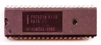
A while ago I bought an old box with integrated circuits that had been stored for many years and contained a lot of tubes with very old IS’s. As I like to build old processor boards and try to repair old computers and boards, these chips were very welcome. In one tube there were two original P8052-Basic chips and that brought back good memories of the time mid 80ties of last century when I was working as head R&D embedded programmer and hardware designer for a small company and was using the 8031 processor a lot. I even extended a tiny Basic version at that time, but the real P8031-Basic was incredible and complete, but expensive and hard to get at that time. I put these chips in my computer chips and cpu collection and one I kept aside to make a board to get it working again. I had a latch and a memory chip in my workshop, a PCB was also there, I only needed to order a few 11.0592 crystals as these are not so common anymore. After two evenings of wiring it was finally ready and at my first attempt to run it I got a line number error all the time. I seemed that the external sram was not working and it was a small wiring error. After I had fixed that it worked like a charm, I connected it to my VT100 terminal with the TTL serial input and after pressing the spacebar I got the prompt and I could write a small Basic program. On this page I will show you the schematic I made, some build instructions and some documentation and (source)code. Regards, Hein Pragt.

I also have a Facebook Group on Retro Computing and Electronics, feel free to join!Intel 8052-Basic chip

Why do we need at least 3 chips

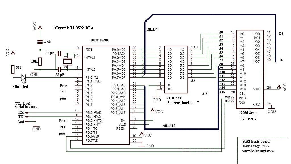
To answer the question why we need al least 3 chips I have to explain the 8031 bus a little. To make room for as many I/O pins as possible Intel decided to multiplex the low part of the addresses and the 8 bit databus on one port. This would mean only 8 pins of the chip instead of 16 pins. Of course you would need an external latch for decoding the 8i address bits and the chip needed a pin to signal the output of the address part. Port 1 is actually a 8 bit data out and a 8 bit data in and a 8 bit address out port. The 74573 chip is often used as an 8 bit latch, this will store the 8 bits and save them (kind of like a 8 bit memory chip) to provide the lower 8 bits of the external memory address when reading or writing to external memory. Then we need a external memory chip, we can use anything between 8 and 128 x 8 sram chips, I chose the 32kb x 8 chip (62256) as I had these laying around. I use A15 as a chip select signal, the chip select pin is active low, so the A15 pin selects to lower 32Kb part. When using other chips you have to figure out yourself how to select the chip and put the unused address lines to ground. This is the minimum configuration and all we need to add are a small reset circuit and the crystal oscillator circuit and were done. Below is my schematic I made of my design.

8052 Hp

Building the board

When building this I use a PCB board that is double sided and not too small so I have room to wire the circuit. I put all the chips in sockets, to be able to reuse them again and protect the chips when soldering. I first put the sockets on the board and leave enough space between them for the wires, then I solder the sockets. Then I solder four pin connectors in one corner, two for the power +5v and Gnd, and two for the Tx and Rx lines. Then I solder the crystal near the processor pins, leaving room for the capacitors and I solder them to the correct pins of the processor socket. Then I do the same with the reset capacitor and resistor.

20220521 221504

The next thing is wiring and soldering all the power lines, I use red wire for the +5V and black wire for the Ground. I use solid kernel wire that is available in a lot of colors. I avoid going over the soldering points and like using a PCB layout go around the chips as much as possible. After this I wire the control and chips elect R/W lines using gray / white and orange wire. Then I take yellow wire and connect all the address lines, I try to keep the wires as much together as possible. Now it becomes a little tricky as the AD lines need both a address and a data latch wire. I use blue for the data latch and green for the databus lines. First I solder the blue wire to the socket pin and then carefully on top of that the second green wire. Make sure you do not use to much solder otherwise you can short two pins. I you shorted two pins, take the solder od with a solder pump and try again.

20220521 220244

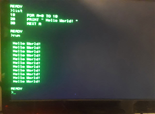
Now all the lines are attached it is time to check for short circuits, take a Ohm meter and put the pins on two socket pins near each other and do that for all pins. If there is no short circuit we can place the chips. Check the powerlines for short circuit before putting 5 volt on the board. I use a USB power supply and I cut a standard USB cable ands solder female sockets on the power lines, safe an cheap. Now connect the board to a terminal or to a PC using a TTL RS232 to USB cable and type space. When all is right you should see a basic welcome message and prompt. The basic manual download link is at the bottom of this page, have fun!
20220521 220213

Using a AT89c52 or STC89c52 chip

The P8052-Basic chip is very rare and not available anymore, but there us a good alternative. Intel made the Basic code freeware a while ago and put the sourecode and hex files on their FTP site. I cannot find it anymore, but luckily I download everything that is interesting and so I have put the original zip file on my website to download. It contains the sourcecode and the binary hex file of the 8Kb Basic interpreter. When you use a 8052 with Flash eeprom like the 89c52 you can burn the hex code inside the microcontroller and you will have the same chip as the P8052-Basic chip. So you can build this small computer with modern parts.

8052 Basic PCB

I have a PCB for a very complere 8052 Basic computer in my webshop. This is a PCB of a Basic computer based on intel p8052-ah basic for the RCBus. (RC2014), an improved basic version for the 8052 was published in ELEKTOR 2001 (MCS BASIC-52 V1.3) This board can hold many different 8052 variants and supports a lot of different crystal oscillator configurations from 11.075 Mhz (Original) up to 22 and even 33 Mhz. The designer flashed the code into an ds89c450 running at 22.184 mhz, and that is 12x faster than an normal 8052. I build mine with a AT89C52 processor, but ANY 8052 version with at least 8Kb internal Flash will work. https://www.heinpragt.nl/?product=8052ah-basic-pcb-rc2014

My 8031 background

In 1986 I started to work as an embedded programmer and hardware designer for a small company in the Netherlands that build modems and computer equipment. At first it was only my favorite processor the Z80 but in the low cost modems we needed a cheaper microcontroller so one day I got a 8031 hardware emulator from Intel with all the development tools. As Intel provided PL/M and Assembler with their development kit I started to program in PL/M and assembler for the 8031 processor. I really fell in love with this processor and struggled to get all the code into a single eprom and only use the internal ram. In the second modem I got a 8032 so that gave me 128 bytes of extra ram and in the next redesign we implemented an Atmel version so we needed no external eprom anymore, bringing the chipcount down. In one of the last devices I build with the 8032 I had implemented the tiny Basic as well to make the device a programmable communication controller. After that we started to make modems with V42/v42bis and MNP compression and the 8032 was not powerful enough, so we stated to use an Intel 80188 processor. But I loved the MSC-52 processors from Intel, but the next companies I worked for used the Z80 and MC6809 chips, so I have used and programmed a lot of different processor chips.

8052 and 8052-Basic related documents

More pages on embedded software

[catlist name=”Embedded software”]
Posted on Leave a comment

8052 processor IDE

8052

This is a page about my freeware 8051 / 8052 IDE program which is an editor / emulator / debugger / assembler / disassembler / ISP programmer for the 8052 all in one portable Windows executable. Many years ago when I was programming the 8052 professionally and at home, tools were very expensive. There was not much freeware or opensource, but trough my employer I had most of the tools I needed. I wrote a lot of programs in 8052 assembler in 8052 assembler and PL/M, but I also learned to write in C and I had a good C compiler for the 8052. The 8052 was a genius design for its time and its funny that this processor is still used a lot. For development and debugging 8052 assembler code, this freeware IDE can be used. Regards, Hein Pragt.

I also have a Facebook Group on Retro Computing and Electronics, feel free to join!

8052 editor / assembler / emulator / debugger

8052 Workbench

To be able to program for the 8052 you need an assembler or compiler. I personally still like to write in 8052 assembler but I could no longer find tools for Windows 10. There were still some programs to download but most of them worked at DOS level, had serious bugs or did not fit my needs. After some searching I decided that it was time for a new project, building a complete integrated 8052 development environment. I found a pretty good assembler and the base code of my Z80 IDE and I had some olde code in my code library. The result is 8052 workbench, a portable x64 Windows program that includes an editor, assembler, disassembler, emulator, single step debugger, Intel hex read / write function a VT100 terminal window, a seven segment display with 8 LEDs and keyboard support.

Installation

Download the zip file and unzip it at the place where you want to install it on your hard drive. Then create a shortcut to the program to the desktop and the program is ready for use. It is a so-called portable program which means that it does not use external sources or libraries and does not use the registry. After removing the directory from this program, it has also disappeared completely from your system.

First time use

To practice there is an example4.asm file in the example directory, which you can load after which it will be in the shown in the middle edit window. Now you can convert this into machine code by means of the assemble button, this will appear on the left of the screen and be put into the virtual memory of the emulator. The last (or first) .org statement will also be put in the program counter and by simply pressing the run button you can execute the program and follow it on the screen. This will not be very fast because every instruction will perform a screen update of all registers. If you want the program to run faster, you can disable the update of the registry block by means of the update checkbox. You can now modify the program, reassemble it and run it again.

In de example directory there are also two 8052 Basic versions from Intel that will run fine in this IDE emulator. After the assembler and RUN hit the spacebar (just as in the original autobaud detect) and the prompt will be shown.

There are more example files, a lot of them I made myself when testing the IDE and some I found on the Internet and are free to use.

By means of the step button you can execute the program instruction by instruction and check the output and the registers. You can also enter the break address, the emulator will then stop at a run command at this address and display the registers of that moment. When 0000 is entered in the break field it will be ignored.

You can save the modified code as an asm file again but also save it as a hex file so that you can load the binary code in a circuit or ep(rom) for a real 8052 circuit. You can also read an Intel-Hex file, which will then be loaded into the internal emulator memory. You can also run tis code when you put the correct start address in the program counter. You can also disassemble this internal emulator memory code after which the source code will appears in the edit screen in the middle. This can then be changed and written back into the emulator memory by means of assemble button.

I/O map

The 8052 has no I/O space so the LEDS and seven segment display are mapped on port 1 and 2. You can put the leds on port 1 or 2 and the display on lines port 1 or 2 and character port 1 of 2. You can select this with the top menu, or with some extra assembler directives I added. Look in the example files to see how they work.

  • The keyboard is send to the serial buffer of the 8052 (SBUF) and the display is also connected to the serial (SBUF) of the 8052. I also pulse the character on the RX pin to enable autobaud detect and simulate the hardware as good as possible.
  • Interrupt lines are connected to the interrupt buttons at the top of the screen, when pushed they will activate the interrupt lines.
  • The output ports are shown at the top as input values and output values, they can be modified to test input / output code.

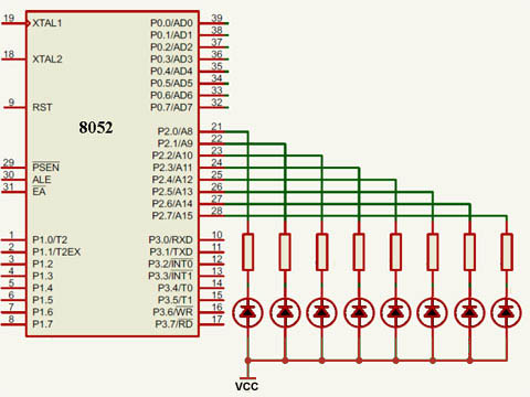
LED I/O modes

In led I/O mode 1 the leds are connected to port 1 and a 1 on the port makes the led light up, directive is ;#LED1

8052 Leds Port1


In led I/O mode 2 the leds are connected to port 2 and a 1 on the port makes the led light up, directive is ;#LED2

8052 Leds Port2

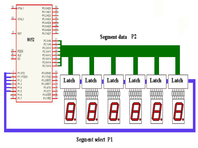
Seven segment display modes

In Seven segment mode 1 the leds are connected to port 1 is select of segment and port 2 is display data. The data is latched so the displays keep their value even if they are no longer selected. Directive is ;#SEVEN12

8052 Seven1


In Seven segment mode 2 the leds are connected to port 2 is select of segment and port 1 is display data. The data is latched so the displays keep their value even if they are no longer selected. Directive is ;#SEVEN21

8052 Seven2

Interrupt pins configuration

The I0, I1 and I2 buttons ar the top of the screen are connected to the interrupt lines to simulate external interrupts.

8052 Interrupts Buttons

User define buttons configuration

There are also four user define buttons on the seven segment panel, these are connected to P1.2 to P1,5 to simulate external switches.

8052 User Buttons

Supported processors

The current version supports the Intel 8031, 8032, 8051, 8052 and Atmel 8952 processor. For the Atmel 8952 processor this IDE had a ISP In Circuit Programming mode, that supports a serial Arduino ISP module to update an 8952 processor from within the IDE. You can edit code, run and debug it on the emulator and then test it on a real 8952 processor. The hardware configuration of the IDE is equal to a cheap 8952 development board from China.

Supported development board

I use this development board, you can order it in my webshop, its very complete, you have to solder it yourself. It had a Zif socket for the processor, a full rs232 circuit, and USB circuit, four pushbuttons and a reset button, am ISP programming connector, eight output leds, a power supply, crystal in socket and all I/O lines on connector pins.

8952 Developme Board

Link: https://www.heinpragt.nl/?product=avr-development-board-kit

Schema of this development board

Development Avr51

8952 ISP programmer using Arduin nano

I created my own Arduino Nano based ISP programmer for the 89S52 processor. I connected it to the Chinese development board with a standard ISP connector cable and I guess this will work on other 8052 ISP development boards as well. I chose this development board because it is very cheap and has a lot of features. And of course an Arduino Nano is small and also cheap.

8959 Arduino Nano Isp

Schema of Arduino Nano ISP programmer

Arduino Nano 8952 Isp Schema

Download Arduino Nano sketch for the ISP programmer.

*) This will also work with an Arduino Uno board!

Version 1.04

I use the 8052_workbench myself and that is one of the way I find and fix bugs. One of the last things I did was recode de TB31.asm file, a complete Tiny Basic interpreter for the Intel 8031 and made it work fine on 8031 with 128 bytes internal ram. During this process I found some little bugs in de emulator and I added a mode to emulate a real 8031 (128 bytes memory checks) to the code. Also I fixed code that would destroy the user interface if there was too much output to the windows. And the most important new feature is the ISP In Circuit Programming option. The example directory now also contains the Intel 8052 floating point basic assembly sourcecode, the complete 8031 tiny basic assembly sourcecode and the paulmon21 assembly sourcecode. I proudly present version 1.04 of the 8052 developer IDE.

Download

Here you can download the latest version if this IDE. This download is a zip file containing a portable x64 (and a x32 version) Windows exe programs, an assembler directory and a examples directory. After weeks of debugging I think the project is ready for release, if you find any bugs please report them to me.

https://www.heinpragt.nl/?product=8052-processor-ide

  • Version 1.04
    • Added full timer 2 support.
    • Added ISP upload feature
    • Change Led polarity to match development board.
    • Added four buttons to LCD panel.
    • Fixed P3 display in register panel.
    • Fixed windows corrupt on to much update.
    • Fixed SETB to handle LEDS correct.
  • Version 1.03
    • Fixed error in IDE update windows that would destroy the IDE context menus.
    • Fixed ADDC flags error.
    • Fixed MOVC A,@A + PC instruction.
    • Fixed DA A instruction AC flag error.
    • Fixed SUBB OV flag error.
    • Added 8031 emulation checkbox.
  • Version 1.02
    • Fixed a last minute change error in the terminal code that made keyboard not respond.
    • Fixed the name of the example directory.
    • Fixed a unwanted quote character in exampkle4.asm.
  • Version 1.01
    • Initial release, it might be not completely bug free, I will test on, wait for remarks amd release the next version soon.


8052 links, tips and documents

More pages on software development

[catlist name=”Software development”]

Posted on Leave a comment

DIY Intel 8052 Basic computer

8052 basic computer

A while ago I bought an old box with integrated circuits that had been stored for many years and contained a lot of tubes with very old IS’s. As I like to build old processor boards and try to repair old computers and boards, these chips were very welcome. In one tube there were two original P8052-Basic chips and that brought back good memories of the time mid 80ties of last century when I was working as head R&D embedded programmer and hardware designer for a small company and was using the 8031 processor a lot. I even extended a tiny Basic version at that time, but the real P8031-Basic was incredible and complete, but expensive and hard to get at that time. I put these chips in my computer chips and cpu collection and one I kept aside to make a board to get it working again.

I had a latch and a memory chip in my workshop, a PCB was also there, I only needed to order a few 11.0592 crystals as these are not so common anymore. After two evenings of wiring it was finally ready and at my first attempt to run it I got a line number error all the time. I seemed that the external sram was not working and it was a small wiring error.

After I had fixed that it worked like a charm, I connected it to my VT100 terminal with the TTL serial input and after pressing the spacebar I got the prompt and I could write a small Basic program. On this page I will show you the schematic I made, some build instructions and some documentation and (source)code.

My 8052 IDE: https://www.heinpragt.nl/?product=8052-processor-ide

AT89C52 – Basic

The INTEL 8052AH-BASIC is not available anymore and very rare, I have tried to put the code into a AT89C52 processor and after a few tries this worked fine. You can order a AT89C52 with the service that I will pre program the chip. https://www.heinpragt.nl/?product=at89c52-basic

Links and downloads