In this post I will explain how to program am ATTiny25/45/85 MCU. I really like the AVR chips, they are powerful, have enough flash and sram memory and have a lot of build in I/O devices. And the chips come in many sizes that all have the same MCU kernel, but a different number of I/O pins and different Flash/Sram sizes. The ATTiny85 is what I use the most, it has the most flash af the 25/45/85 series and it is rather cheap. The chip has 6 programmeble I/O pins and that is enough for a lot of things. It does not have a serial Uart but if you really need this you can use the software Uart. To program this chip you will need a programming environment, I use Visuals Studio PlatformIO and the old but decent Arduino IDE. Fot beginners I would recommend the Arduino IDE as it is foolproof and easier. With PlatformIO you can control much more (like all the fuse settings in binary format) but if you do something wrong you can get totally unusable bricked MCU chips. On this page I describe an Arduino Uno as ISP programmer.
Arduino Uno as ISP
I have bought a lot of Arduino programmers when I first started and I had a lot of problems with them especially the Chinese clones. Then I discovered the Arduino Uno as ISP and build several shields for 8, 14 , 20 and 28 pins AVR chips. Because all the different sizes of chips have their programming pins on different pins and need the power pins also connected, I build several shields. But they are cheap to make. Hier is the schematic of the shield I use for the ATTiny25/45/85 processor.
I use a standard prototype shield and a ZIF header for this (8 pins zif are hard to get so I use a bigger one and put tape on the unused pins), then first upload the Arduino as ISP scketch to the Arduino Uno. Select the AruidnoISP sketch from the examples and select Arduino Uno as board.
Connect the Arduino Uno using the USB cable and select the correct port in the Tools settings. Then use the Upload button to upload the ArduinoISP sketch to the Arduino Uno and your ISP programmer is ready.
I hope this was clear, if you got anything to add to this post then let me know, regards, Hein Pragt.
In this post I will explain how to program am ATTiny2313 / AT90S2313 MCU. I really like the AVR chips, they are powerful, have enough flash and sram memory and have a lot of build in I/O devices. And the chips come in many sizes that all have the same MCU kernel, but a different number of I/O pins and different Flash/Sram sizes. The ATTiny2313 (or the even cheaper AT90S2313) is just in the middle and I like to use this chip and it is not that expensive. To program this chip you will need a programming environment, I use Visuals Studio PlatformIO and the old but decent Arduino IDE. Fot beginners I would recommend the Arduino IDE as it is foolproof and easier. With PlatformIO you can control much more (like all the fuse settings in binary format) but if you do something wrong you can get totally unusable bricked MCU chips. On this page I describe an Arduino Uno as ISP programmer.
Arduino Uno as ISP
I have bought a lot of Arduino programmers when I first started and I had a lot of problems with them especially the Chinese clones. Then I discovered the Arduino Uno as ISP and build several shields for 8, 14 , 20 and 28 pins AVR chips. Because all the different sizes of chips have their programming pins on different pins and need the power pins also connected, I build several shields. But they are cheap to make. Hier is the schematic of the shield I use for the ATTiny2313 / AT90S2313 processor.
I use a standard prototype shield and a ZIF header for this, then first upload the Arduino as ISP scketch to the Arduino Uno. Select the AruidnoISP sketch from the examples and select Arduino Uno as board.
Connect the Arduino Uno using the USB cable and select the correct port in the Tools settings. Then use the Upload button to upload the ArduinoISP sketch to the Arduino Uno and your ISP programmer is ready.
I hope this was clear, if you got anything to add to this post then let me know, regards, Hein Pragt.
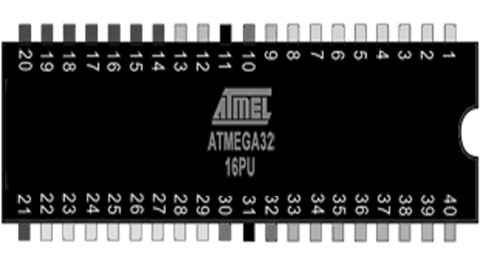
In this post I will explain how to program am ATMega32A MCU. I really like the AVR chips, they are powerful, have enough flash and sram memory and have a lot of build in I/O devices. And the chips come in many sizes that all have the same MCU kernel, but a different number of I/O pins and different Flash/Sram sizes. If you really need a lot of I/O pins the ATMega32A is what you need, I like to use this chip and it is not that expensive. To program this chip you will need a programming environment, I use Visuals Studio PlatformIO and the old but decent Arduino IDE. Fot beginners I would recommend the Arduino IDE as it is foolproof and easier. With PlatformIO you can control much more (like all the fuse settings in binary format) but if you do something wrong you can get totally unusable bricked MCU chips. On this page I describe the Arduino IDE with an Arduino Uno as ISP programmer.
ARDUINO IDE
I really liked the Arduino IDE until the last versions. The (configuration / libraries) directories it uses are all over your disk and hard to find. That is why I recommend the portable arduino-1.8.19 version. This has all the files in a single directory. Install this version somewhere on your drive and it works out of the box. But out of the box it does not support the ATMega32 processors. There are several solutions that depend on your version of the Arduino IDE, find one that fits your IDE and install it. I have included this standard in my portable version of the Arduino IDE.
Arduino Uno as ISP
I have bought a lot of Arduino programmers when I first started and I had a lot of problems with them especially the Chinese clones. Then I discovered the Arduino Uno as ISP and build several shields for 8, 14 , 20 and 28 pins AVR chips. Because all the different sizes of chips have their programming pins on different pins and need the power pins also connected, I build several shields. But they are cheap to make. Hier is the schematic of the shield I use for the ATTin24 processor.
I use a standard prototype shield and a ZIF header for this, then first upload the Arduino as ISP scketch to the Arduino Uno. Select the AruidnoISP sketch from the examples and select Arduino Uno as board.
Connect the Arduino Uno using the USB cable and select the correct port in the Tools settings. Then use the Upload button to upload the ArduinoISP sketch to the Arduino Uno and your ISP programmer is ready.
Programming an ATMega32A
First we start by loading (or writing) the sourcecode file of the ATMega32 code in the programming language C in the Arduino IDE. Then go to the tools setting and select the correct device. Under tools select the configuration of the ATMega32A you will use, in my case an ATMega32 with external 16 Mhz clock.
// -----------------------------------------------
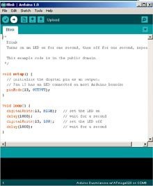
// Blink for ATMega32A
// H.M. Pragt 2022
// -----------------------------------------------
#ifndef F_CPU
#define F_CPU 16000000UL // 16 MHz clock speed
#endif
#include <avr/io.h>
#include <util/delay.h>
int main(void)
{
DDRD = 0xFF; //Makes PORTD as Output
while(1) //infinite loop
{
PORTD = 0xFF; //Turns ON All LEDs
_delay_ms(2000); //1 second delay
PORTD= 0x00; //Turns OFF All LEDs
_delay_ms(2000); //1 second delay
}
}
Now the last setting is selecting to use the ArduinoISP programmer:
Connect the Arduino Uno with the shield and the ATMega32A chip inserted to the computers and select upload button to program the code into the chip. As easy as that, happy programming.
I hope this was clear, if you got anything to add to this post then let me know, regards, Hein Pragt.
In this post I will explain how to program am ATTiny24 (or 44,84) MCU. I really like the AVR chips, they are powerful, have enough flash and sram memory and have a lot of build in I/O devices. And the chips come in many sizes that all have the same MCU kernel, but a different number of I/O pins and different Flash/Sram sizes. I like to use the ATTiny85, it has 8 pins but of 6 I/O lines are enough this is a perfect MCU. The ATTiny2313 has 20 pins if you need more I/O lines, but the ATTiny24 has 14 pins and is cheap and has 12 programmable I/O lines. The small size with 12 I/O lines makes this one of my favorite AVR chips. To program this chip you will need a programming environment, I use Visuals Studio PlatformIO and the old but decent Arduino IDE. Fot beginners I would recommend the Arduino IDE as it is foolproof and easier. With PlatformIO you can control much more (like all the fuse settings in binary format) but if you do something wrong you can get totally unusable bricked MCU chips. On this page I describe the Arduino IDE with an Arduino Uno as ISP programmer.
ARDUINO IDE
I really liked the Arduino IDE until the last versions. The (configuration / libraries) directories it uses are all over your disk and hard to find. That is why I recommend the portable arduino-1.8.19 version. This has all the files in a single directory. Install this version somewhere on your drive and it works out of the box. But out of the box it does not support the ATTiny processors. Install a ATTiny core package like the https://github.com/damellis/attiny (I used this one). On this website is also an installation manual so I recommend you follow this. After this you will have a Arduino IDE that can program ATTiny24 / 44 / 84 chips. I have included this standard in my portable version of the Arduino IDE.
Arduino Uno as ISP
I have bought a lot of Arduino programmers when I first started and I had a lot of problems with them especially the Chinese clones. Then I discovered the Arduino Uno as ISP and build several shields for 8, 14 , 20 and 28 pins AVR chips. Because all the different sizes of chips have their programming pins on different pins and need the power pins also connected, I build several shields. But they are cheap to make. Hier is the schematic of the shield I use for the ATTin24 processor.
I use a standard prototype shield and a ZIF header for this, then first upload the Arduino as ISP scketch to the Arduino Uno. Select the AruidnoISP sketch from the examples and select Arduino Uno as board.
Connect the Arduino Uno using the USB cable and select the correct port in the Tools settings. Then use the Upload button to upload the ArduinoISP sketch to the Arduino Uno and your ISP programmer is ready.
Programming an ATTiny24
First we start by loading (or writing) the sourcecode file of the ATTinty code in the programming language C in the Arduino IDE. Then go to the tools setting and select the correct device.
Then select the internal or external clock and the frequency.
Now the last setting is selecting to use the ArduinoISP programmer:
Connect the Arduino Uno with the shield and the ATTiny24A chip inserted to the computers and select upload button to program the code into the chip. As easy as that, happy programming.
I hope this was clear, if you got anything to add to this post then let me know, regards, Hein Pragt.
After making several projects with various Arduino boards, I started to use smaller and smaller boards and I ended up with a standalone processor chip. And for some applications, the standard 28-pin chip is still a bit too large. My eye had already fallen on the ATTiny85, but the 8 connection pins scared me off. But after I give the chip a good look and when I had a closer look at it, I noticed its strength. The small chip contains a full Atmega processor with flash programming memory and RAM on board with also a built-in crystal oscillator. So it is a real single chip computer with 6 (5 effective when you want to keep the reset pin for reprogramming) in or outputs that also have additional functions such as Interrupts, PWM and analog. Each pin is freely programmable for a function and whether you want one input and five outputs or vice versa, it’s all possible with this little chip. But the chip can also communicate using I2Ch, for example to connect a screen or multiple sensors or control lights or motors with the designated PWM output pins. When I started thinking about this, I suddenly saw a lot of possibilities, the chip costs between 1 and 3 euros and can replace a complex electrical circuit. There are also a number of links on this page to sites that have done impressive things with this tiny ATTiny chip. Small boards are available with a USB port with an ATTiny85 on it, but the chip can of course also be used as a standalone chip. To program the ATTiny you will need an ISP programming board, but this is a task that our older trusted Arduno Uno can do for us. On this page there is also a small set-up board for the Arduino Uno with which the ATTiny chips can be programmed from the standard Arduino development environment.
Atmel also markets several models with the ATTiny in different housings. I’m only going to cover the the 8 pins versions here. With larger versions I quickly tend to take the 28 pins Atmega328 again because this chips is almost the same price or sometimes even cheaper. As we are used to from Atmel, there are several versions with different amounts of Flash rom and sram memory with different prices as well. By default they have a built-in RC oscillator that is not super accurate but keeps two pins free, an external crystal can also be used by sacrificing two pins oscillator to be attached. The ATtiny85 works by default on a 1 Mhz built-in RC oscillator but this can be increased by loading of the software.
To program an Arduino you need software, the Arduino programming environment. This free development environment can be found at: download Arduino IDE here . This environment is suitable for Windows, Linux and Mac OS X. When you have connected the computer to the Arduino board wtth a USB cable, you can transfer the program code directly to the Arduino board. You can write the program on your own computer and “upload” the code to the Arduino board. All you need to do is select the board type in the menu and the port you are using on which the board is connected (when there are multiple ports). There is really only one programming language popular for the Arduino and that is the programming language C and C++. The programming environment includes a large amount of standard libraries for LCD, Servo, motors, wifi, etc. and all of these are free to download. The Arduino C version deviates from the C standard on a few points and unfortunately not all functions are present in the supplied libraries. Of course it is still an 8 bit processor and for example the support of double variables is a bit flawed. Where a standard C program starts with a main() routine, an arduino program (often called a sketch) consists of two program blocks, the setup() and the loop(). At the beginning of the program is the “void setup()” and in this function allows initialization of the program such as initialization of I/O pins, initialization of software libraries, and global variables. The setup() function is executed once by the arduino at program startup. Then it is the turn of the loop() function, it will be called endlessly until the power is turned off. From this loop() function you can call other functions and so you can build a structured program.
Arduino ATTiny default pin modes
A common source of confusion appears to be the function and numbering of the in/out pins of the aTtiny processor. I searched myself on the Internet and read the datasheets and came to the following simple overview that makes everything clear. Each pin has a different internal number and function depending on how it is configured with pinMode() and whether one uses analogRead, analogWrite, digitalRead or using digitalWrite. To make it clear I have put this in an excel sheet of which a printout is here. You don’t have to go through the internet registers to program the function of the pins, unless you want to use the alternative functions of the pins. The standard IDE and the chip definition herein will do most of the work for you when you specify the pins in the standard way.
To be able to program the ATTiny, you need an ISP programming board and these are also available in various versions. These programmers are not cheap and if we already have an Arduino Uno, we can easily use it as an ISP programmer as an extra task. You can build a small circuit on a breadboard every time you want to program an ATTiny, but when you you want to program more often, a small shield for the Arduino Uno is more convenient. We build this on a small piece of experiment print and you will need a pair of header pins, an 8 pin IC socket, a LED, one 220 ohm resistor and a 10 uF capacitor. And of course a soldering iron, solder and mounting wire, preferably in different colours. I chose to put the solder side up, this makes soldering the headers much easier and the rest of the components can just as well be soldered on the top side. The connection wires are then hidden at the bottom.
I sawed off a piece of experimental PCB of 10 holes wide and 20 holes long. On one side is the (8) row of pins are on the far left and the other side all the way to the right. I plugged the pin rows into the Arduino first. On the power supply side and the reset pin I use the entire set of last pins, the unused pins serve as reinforcement. To polarize the board to prevent it from putting it in the wrong way I added two femnale header pins next to the male ones. On the other side the row of pins ends at the middle separation, leaving two pins free at the usb connector. Then I push the PCB over the pins and I carefully solder the pins. Don’t use too much solder, we don’t want pins to connect. Then we also bend the pins of the IC socket to the side and solder it somewhere in the middle of the PCB. I put the 1 pin on the side of the USB and power plug myself and marked it extra with a thick tip of a black marker. Then the PCB can be removed from the Arduino Uno. At the top of the PCB (the solder side) we now put the LED and the resistor between the negative supply voltage pin and pin 5 of the ATTiny socket. Please pay attention to the polarity of the LED, you can test whether it is seated correctly by putting the plus on the pin of the foot and the minus on the header pin. Now we can do it turn the PCB over for the rest of the wiring.
We now connect pins of the power supply to the IC socket, the plus 5 volts goes to pin 8 and the Gnd to pin 4 of the socket. Now we can solder the small capacitor of 10 uF between the Gnd and the Reset pin of the Arduino Uno pay attention to the plus and the minus of the capacitor (minus to Gnd) and place the capacitor a little parallel to the header pins so that it will be sits neatly next to the Arduino chip. Now we solder the remaining wires between the Arduino Uno pins and the IC socket. Which Arduino pin to which pin of the foot is shown in the diagram below. Pay particular attention to using little solder so that there is no short circuit and if necessary, use the tip of a small screwdriver between the solder spots to remove small tin residues. Then we are going to test whether everything works by inserting an ATTiny into the socket and plugging the shield onto the Arduino Uno. Now connect Uno to the computer with a USB cable, the Arduino Uno should work normally and the shield will do nothing. To switch the Arduino Uno to ISP programmer, let’s take the shield off again.
Adjust the Arduino IDE
To be able to program the ATtiny85 we first have to upload the ISP sketch in the Arduino Uno. You can find this sketch in example files included with the Arduino IDE which can be found in file -> Examples and the sketch is called ArduinoISP. Connect the Arduino Uno without shield to the computer and upload this sketch to the Arduino Uno in the usual way. Now let’s get the Arduino the IDE to support the Attiny. In the screen that you can find under File -> Preferences, search for the input field “Additional Board Management URL” and enter the following URL:
Then press the OK button to save the setting and close the screen. Then go to Tools -> Board -> Board Manager and search all the way down to the block that says “attiny by Davis A. Mellis” and click install. After installing, you should see a new board in the selection screen for the boards. Here you select the board, the processor and the choice for Arduino as ISP and then you put the shield on the Arduino. Now you can load the Blink sketch where you have to change the LED pin to 0 because we have the LED on this pin. When you connect the Arduino with the shield to the computer you should be able to upload this sketch using the normal upload button to the ATtiny, after which it will flash happily. This didn’t work for me at all and the IDE gave an error about a device number 00000, after checking it turned out that a solder connection on the IC socket was not good. After this it works fine and I could use my ATtiny85 with the blink sketch.
ATtiny with external crystal
I made a small extension to my programmer board. In one of my first experiments I made a mistake and I accidentally installed a bootloader with an external crystal after which the attiny85 chip stopped responding. So I couldn’t use the bootloader to make the ATtiny85 work on the internal oscillator again. The bootloader sets the “fuses” that determine whether the chip uses an internal or external clock. If the chip is set to external and there is no crystal, the chip will not boot. The only way to reprogram the chip is to connect an external crystal. So I decided to install an external crystal of 8 Mhz on the PCB in a small socket so that I could remove it again for checking. The crystal has a a 22 pF capacitor to ground on both legs. The capacitors can remain in place when the crystal has been removed. After placing the ATtiny85 on the board with the crystal, I selected the 1 Mh internal boatloader that I could then upload successfully after which the Attiny also worked without the crystal. By means of this extension I can now also load code that will use eventualy use an external crystal in the final circuit of the Attiny processor.
I bought a PICKIT3 In Circuit Programmer unit and a dev board, but that was only for 40 pins PIC chips and I also want to use 28 pins PIC chips, for smaller designs that do not need so many pins. I looked in several shops but could not find anything that would fit my needs, so I decided to design and build one myself. It is not that hard, there are lot of example designs and after looking at them I had a good idea of what I wanted. So after one night designing and two nights soldering, I was finally able to test my design. I works like a charm.
It has a 40 pins ZIF socket and a 28 pins ZIF and all programming lines, onboard LED and switch are shared by both sockets, and a reset button that is shared by both sockets, but every socket has its own crystal oscillator circuit. It has a USB power supply, but during programming the power comes from the PICKIT3 device. It has a power indicator led, and two header rows of ground and plus 5 volt, to power devices you want to connect. I put header pins beside both sockets (both sides) so that every pin of the PIC processor is available to devices you want to connect. The onboard led is on pin RA0 and the switch is on port RE2 with a pullup. Both led and switch are connected to the PIC with a jumper so they can be disconnected if they are in the way.
There is one big restriction, you can only have ONE chip on the board, never two at the same time because the pins are hardwired together.
The board also has both the TX and RX lines (and Ground) on a header so you can connect it to a serial port using an TTL to RS232 cable. The crystals of the oscillator circuit are placed in a header pin socket so they can be replaced easily, I use 4 Mhz crystals (just like the original dev board), but you can choose anything that fits your needs and matches with the PIC processors.
I use MPLAB as a development suite and I can connect MPLAB with the PICKIT3 adapter to this board, edit my ‘C’ source code and upload it to the PIC processor on my dev board with just one click. This makes PIC processor development nice and easy.